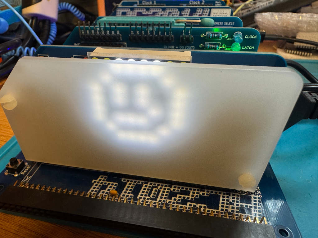
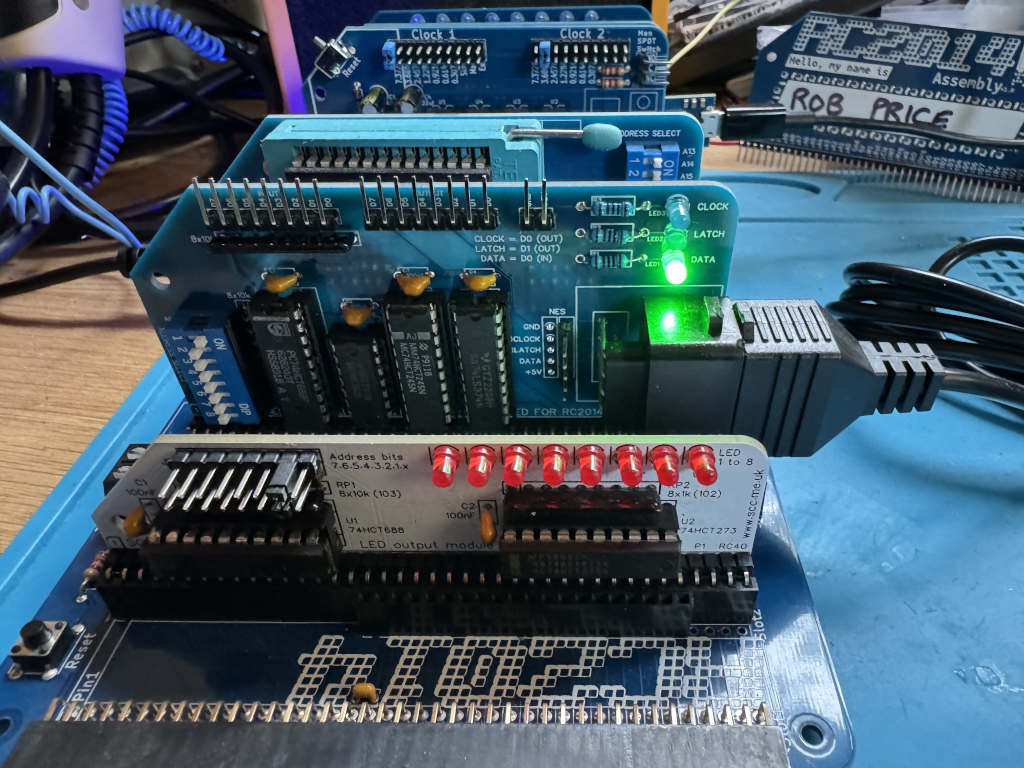
I previously controlled a MAX7219 LED matrix over SPI from my RC2014 computer. Now I want to try another SPI device, the BM280 environmental sensor from Bosch. The code in this article builds on the previous work, so take a moment to read it if you haven’t already.
The BME280 can read temperature, pressure, and humidity. It is a 3.3V device, so I will need a voltage level converter to use it with a 5V RC2014.
The SPI communication will also need to be two-way, as I will need to tell the sensor what values to send me.
I used the following parts (note: Amazon affiliate links)
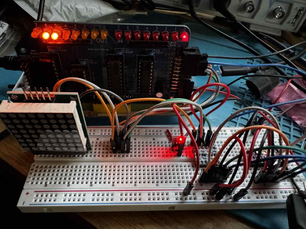
The regulator allowed me to generate a 3.3v power supply from the RC2014’s 5v supply. I was then able to use this on the low-voltage side of the level shifter to allow the signals to convert between 5v and 3.3v.
As before, I am using the SC129 Digital IO module on my RC2014 to bit-bang the SPI protocol. This is wired up via the level shifters and 3.3V regulator as follows…
SC129
BME280
GND
GND
5V
3.3V (via 3.3 regulator)
OUT D0
SDA / SDI (via level shifter)
OUT D1
SCL / SCK (via level shifter)
OUT D3
CSB (via level shifter)
IN D0
SDO (via level shifter)
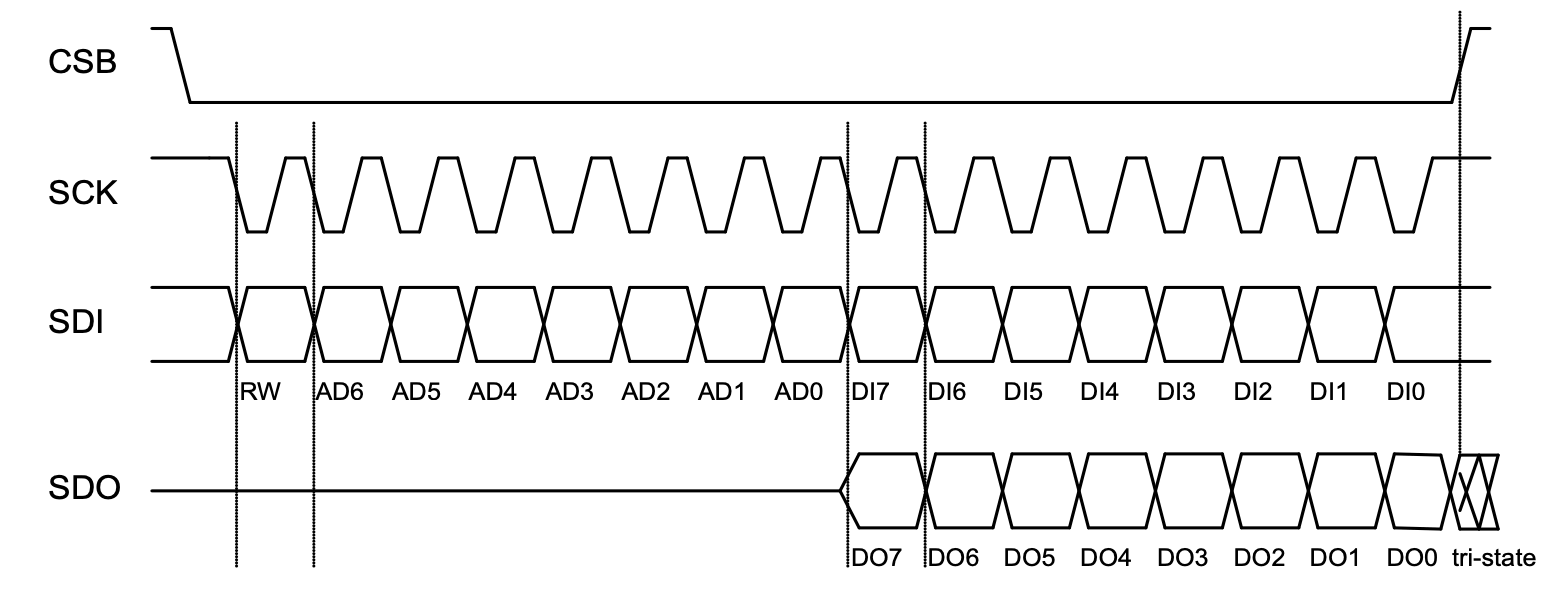
The BME280 gives us the following timing diagram for SPI communication.
Looking at the timing diagram, we can see that before we start any communication, the SCL / SCK and CSB lines both need to be high. We can use a subroutine to do this.
deselect_bme280:
    ld a, 0 | SELECT | CLK | MOSI
    out (OUTPUT_PORT),a
    ret
Sending and receiving take place on the transition of the SCK line from high to low.
This code is similar to the code for the LED matrix in my earlier post. I have added some additional code to handle the input. This reads the bit, rotates it right into the carry flag, then rotates that value into the E register. By the end of the routine, the byte in register D will have been sent, and the byte returned will be in register E.
send_receive_byte:
    push bc
    ld b, 8
    ld a, 0 &~SELECT &~CLK | MOSI
    rra
    ld c, a
.transmit_bme280_bit:
    ld a, c
    rl d
    rla
    out (OUTPUT_PORT), a.  ; CLK low
    in a, (INPUT_PORT)
    rra
    rl e
    ld a, c
    or a, CLK
    out (OUTPUT_PORT), a   ; CLK high
    djnz .transmit_bme280_bit
    pop bc
    ret
To test that this is working, we can send the value 0xD0 to the BME280. It should send back the value 0x60. To read the returned byte, we send 0x00. While this is being sent, the result byte will be returned simultaneously. We will then output this byte to the SC129 so the display LEDs will show the returned value in binary.
bme280_getId:
    call deselect_bme280
    ld d, 0xD0
    call send_receive_byte
    ld d, 0x00
    call send_receive_byte
    call deselect_bme280

    ld a, e
    out (OUTPUT_PORT), a
    ret
After running, the LEDs correctly show 01100000 – 0x60.
The next step will be to get actual temperature readings. That will be the subject of the next post.
The first device I want to use is an 8×8 LED matrix (Amazon affiliate link). Shelia Dixon has previously developed an 8×8 LED matrix display module for the RC2014; however, this is directly interfaced to the RC2014 using two IO ports. I will be using a single port and communicating with it by bit-banging the SPI protocol.
MAX7219 LED Matrix
The 8×8 LED matrix I’m using is a MAX7219 to handle the SPI communication and control the LEDs. It uses 5 wires from the RC2014
VCC – +5V
GND
CS – Chip Select – This is active low
CLK – Clock – Data is loaded when the clock goes from low to high
DIN – Data In – 1 bit of data
I’m using the SC129 Digital IO module from Small Computing Central on the RC2014 for the digital output. This provides pins suitable for DuPont connectors. You could use the official RC2014 Digital IO module, but you would have to modify it to add connections. In this case, it’s simpler to use the SC129 module. The SC129 is connected to the LED matrix module as follows…
SC129
MAX7219 LED Matrix module
+5V
VCC
GND
GND
OUT D0
DIN
OUT D1
CLK
OUT D2
CS
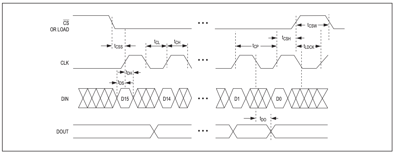
The MAX7219 gives us this timing diagram to follow when we want to send it data.
So to send data, we need to first take the CS line low. This activates the MAX7219, and it knows to listen for incoming data. Next, we set DIN and take CLK high. This will load the single bit of data on DIN into the MAX7219. Now we take CLK low in preparation for the next bit to be sent. We repeat this 8 times in total to send a byte of data.
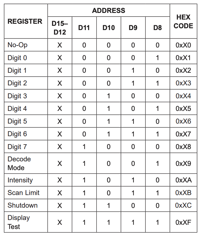
The MAX7219 expects two bytes of data to be sent each message. The first byte is an address, the second byte is the data value.
Sending SPI data using the Z80
So how do we do this on the Z80? Well, first we’re going to define some constants to help.
The SC129 is using IO Port 1.
OUTPUT_PORT EQU $01
As we said earlier, the Data bit is D0, the Clock is D1, and the Select line is D2. We call the Data bit MOSI, which stands for Master Out Slave In.
As you can see, we’re using binary to define the location. When we want to set the bit in one of these positions, we can use an OR statement, and when we want to clear the bit, we can AND the Compliment (the inverse).
So to enable the MAX7219 we want the SELECT line to be low, the CLK line to be low, and we will take MOSI high. We can use the following Z80 subroutine to do this.
select_max7219:
    ld a, 0 & ~SELECT & ~CLK | MOSI
    out (OUTPUT_PORT),a
    ret
To disable the MAX7219, we want the SELECT line to be high, the CLK line to be low, and we will take MOSI high.
deselect_max7219:
    ld a, 0 | SELECT & ~CLK | MOSI
    out (OUTPUT_PORT),a
    ret
To send a byte, need to send 8 bits of data. We pass the byte we want to send in the D register. To send a bit of data, we know we need to take SELECT and CLK low. We can prepare this and save it to the E register to reuse each bit. We are going to be shifting data into the MOSI bit, so before we save it to e, we shift it to the right. Now, for each bit we want to send, first load the A register with the value of the cached E register. We then pick up the next bit from the d register by shifting d to the left. This pushes the bit we want to send into the carry flag. We retrieve it by shifting the A register to the left so it sets the value of the carry flag into the MOSI bit. We send this, before ORing the CLK bit to take it high, and sending that.
That was quite a wordy explanation, but here’s the code so hopefully it makes more sense.
transmit_max7219_byte:
    push bc
    ld b, 8
    ld a, 0 &~SELECT &~CLK | MOSI
    rra
    ld e, a
.transmit_max7219_bit:
    ld a, e
    rl d
    rla
    out (OUTPUT_PORT), a
    or a, CLK
    out (OUTPUT_PORT), a
    djnz .transmit_max7219_bit
    pop bc
    ret
To send a two-byte instruction to the MAX7219, we need to combine the subroutines we’ve built. We need to select the MAX7219, send two bytes, then deselect it. We’ll pass the two bytes in registers b and c.
max7219_write:
    call select_max7219
    call transmit_max7219
    call deselect_max7219
    ret

transmit_max7219:
    ld d, b
    call transmit_max7219_byte
    ld d, c
    call transmit_max7219_byte
    ret
Controlling the MAX7219 using SPI
To tell the MAX7219 to turn on or off a LED, we send a column address in one byte, and the column data in the next. So, 8 columns of bits. However, we also need to send some additional command codes so the MAX7219 knows how to behave.
The MAX7219 can interface with 7-segment displays, but we don’t want any of this functionality, so we need to tell it not to decode any incoming display commands. We also want to make sure it is running on a low duty cycle to reduce power usage.
These are the commands I use to initialise the display.
    ld bc, 0x0C00       ; shutdown mode, this ensures the LEDs are off.
    call max7219_write
    ld bc, 0x0900       ; no decoding
    call max7219_write
    ld bc, 0x0A01       ; 3/32 intensity
    call max7219_write
    ld bc, 0x0B07       ; scan all 7 columns
    call max7219_write
    ld bc, 0x0F00       ; No display test
    call max7219_write
Once setup we can send the image. We send the column number in register b, and the column data in register c. So to send a cross I can use the following.
cross:
    dc %00000000
    dc %01000010
    dc %00100100
    dc %00011000
    dc %00011000
    dc %00100100
    dc %01000010
    dc %00000000
Finally, I turn the display on.
    ld bc, 0x0C01       ; normal operation - turn on the display
    call max7219_write
Building, deploying, and running on the RC2014
To assemble the code, I’m using the SjASMPlus Z80 assembler on my MacBook Pro. The RC2014 is running SCM, so to transfer the assembled code, I need to convert it into Intel hex before sending it across. I use z88dk-appmake to do this. Once across, I run the application using the “g” command in SCM.
So, to assemble my matrix.s source code to address $9000 and send it to my RC2014 using the serial device at /dev/tty.usbmodem03591, I would use the following. First, I would make sure I am connected to the RC2014 over serial using the following…
% minicom -c on --device /dev/tty.usbmodem03591
Next, I would open another Terminal shell and run the following…
Going back to minicom, I execute the code using the following…
g 9000
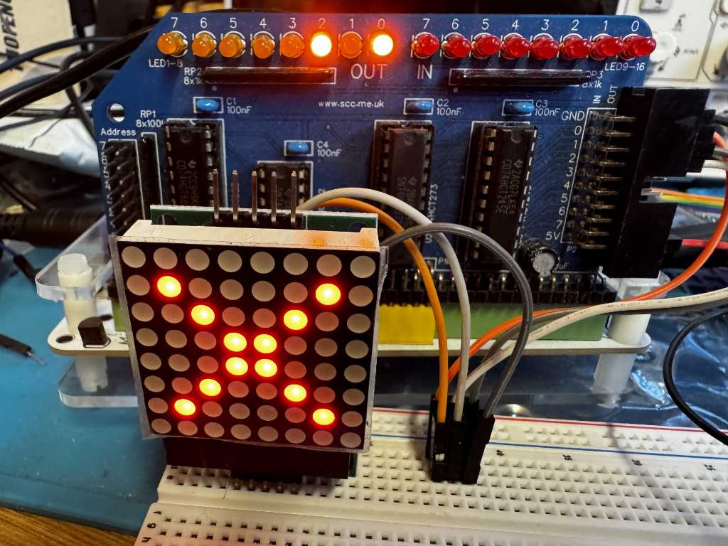
This will run the transmitted code, and my image will appear on the LED matrix.
Update
It’s been pointed out to me that the newer versions of SjASMPlus support the building of Intel HEX files directly, so we can skip the z88dk-appmake step. To build the hex files in SjASMPlus, we can use the following…
After taking part in the very enjoyable RetroChallenge in 2024 and 2025, I’ve decided to take part again in 2026.
This year, my plan is to use the SPI prototcol so my RC2014 computer can talk to various other SPI supporting devices.
SPI stands for Serial Peripherial Interface. It uses synchronous serial communication allowing a “master” to talk to “slave”. This gives us two lines MOSI – Master Out Slave In, and MISO – Master In Slave Out. There is a also a Clock line where 1 bit of data is sent and received each pulse of the clock, and a Select line that is used to activate a device. This allows multiple devices to share the same Clock, MOSI, and MISO lines, while using individual Select lines.
The Z80 microprocessor the RC2014 uses does not natively support SPI, so I will need to put together some basic hardware as well as writing software to support it.
I’ve recently become interested in how ROM cartridges work on the ZX Spectrum. They were initially introduced by Sinclair Research with the release of the ZX Interface 2. This was a joystick interface that supported two Atari style 9 pin joysticks, and included a slot for a ROM cartridge. When a ROM cartridge was inserted and the Spectrum powered up, the internal ROM in the Spectrum would be disabled and replaced with the ROM in the cartridge. This meant games or other code on the cartridge would run instantly without needing to be loaded from cassette. However, it also meant games could not rely on any routines in Spectrum ROM, and must be standalone. The ROM cartridge is 16 kilobytes in size.
Looking at Jurl, the binary is 27,353 bytes in size. This is larger than the 16k size limit of the ROM cartridge. However, we can use compression to squeeze Jurl so it fits into a 16k cartridge. If we use ZX0 compression, we can shrink Jurl down to just 11,598 bytes.
Let’s start to put our ROM code together.
The code on the ROM will always start to execute from address 0. We can’t be sure the contents of the RAM will be blank. We could zero all the contents of the RAM, but it would be quicker to just make sure the BORDER, PAPER, and INK are all set to black so the user doesn’t see anything they shouldn’t.
The border is set using a Z80 out instruction to port 254. The paper and ink can be setting the attribute area of the screen memory to 0. This starts at address $5800 and is 767 bytes long. We can use a Z80 ldir instruction to quickly clear this.
; first, set the border to black
    ld a,0
    out (254),a           ; border black

; now set the background paper and ink to black by filling the attribute
; memory with 0s.
    ld hl,$5800           ; attribute memory start
    ld de,$5801
    ld bc,767
    ld (hl),a
    ldir                  ; fill all 768 attributes
Now we have a black screen, we can decompress the game and start it. We set the location of the compressed game in the HL register pair, and the destination address in DE before we call the ZX0 decompression routine. Once the game has decompressed we can just call it. We add a jump back to the call instruction incase the game returns. This ensures the game will just restart.
 ; decompress the game code into memory at gamelocation.
    ld hl,jurldata
    ld de,gamelocation
    call dzx0_standard

; run the game code.
.game_loop:
    call gamelocation

    jp .game_loop
Remember I said that the Spectrum’s ROM was replaced by the contents of the cartridge? Well, this causes a couple of problems as Jurl is expecting two things to be available in specific locations in the ROM. For the game to work, we will need to fix this.
Firstly, Jurl expects the Z80 to be running in IM1. This is interrupt mode 1 which means the Z80 will be interrupted periodically and will execute code at address $38. This would normally handle things like reading the keyboard, but Jurl doesn’t actually do anything with the data the interrupt is handling. This means we just need to handle the interrupt and return. So at address $38 we add the following.
im1:
    ei     ; re-enable interrupts
    reti   ; return
Secondly, Jurl also expects the ZX Spectrum’s font be available at address $3D00. I used the memory dump option in the Fuse emulator to save the font from the Spectrum’s ROM. I can then just include this binary data into my ROM at the correct address.
Once the source code has been assembled, the ROM cartridge binary can be tested in Fuse using the Media -> Cartridge menu option.
Building a physical ROM cartridge
Now I have a working binary, I can create a physical ROM cartridge to use in my ZX Interface 2.
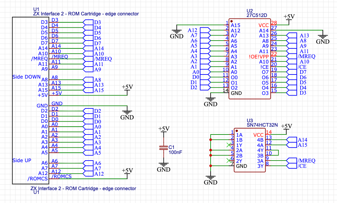
The ROM cartridge slot exposes address and data lines, as well as MREQ. I have several W27C512 EEPROMs I can use in the cartridge. This is a 64k cartridge but as I only need 16k, I can tie lines A14 and A15 to ground. I can also use a 74HCT32 OR gate to enable the EEPROM when A14, A15, and MREQ are all low.
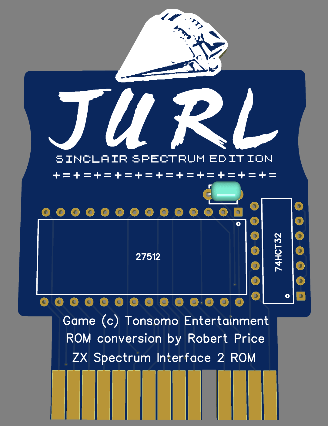
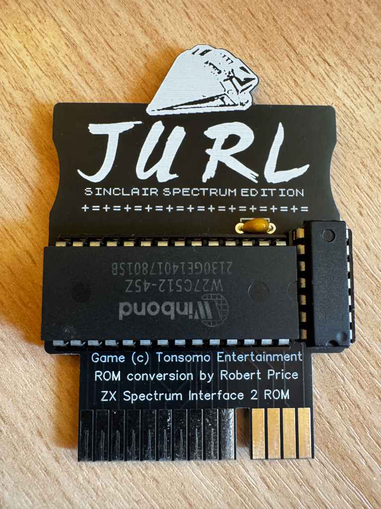
Now I have a circuit, I can use this to create a PCB. I have used EasyEDA to layout the PCB and also include a graphic of the spaceship from the loading screen.
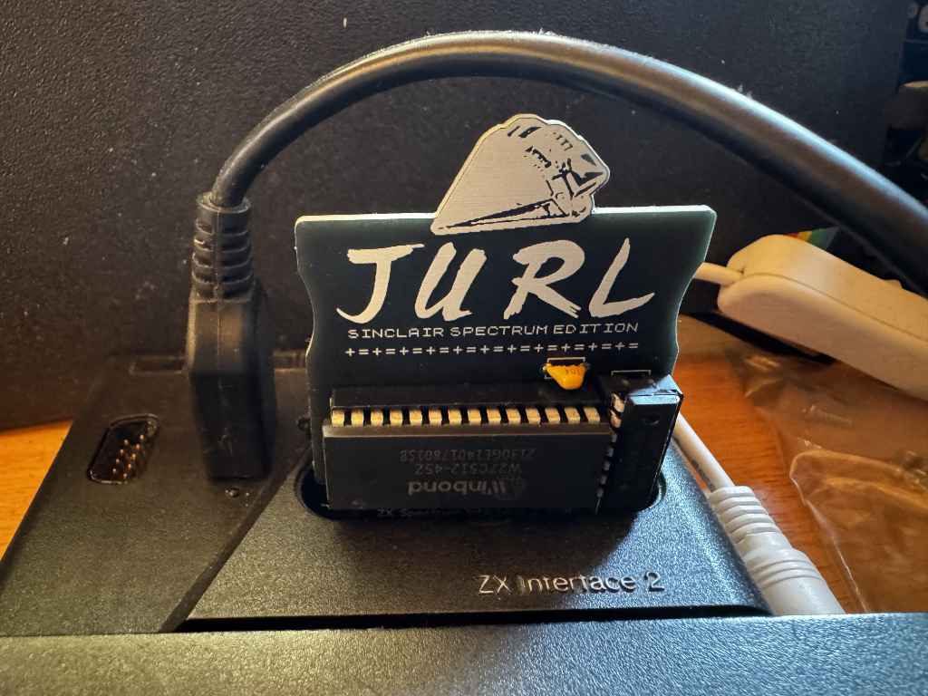
I sent the PCB design off to be manufactured, and when the boards arrived in the post I soldered one up and tested it out.
The card works well, and I now can play Jurl on my 48k ZX Spectrum instantly.
Acknowledgements
Before sharing this project, I wrote to Johnny to get his approval as the game is under copyright. I am very grateful that he kindly gave permission for me to share this.
The RetroChallenge may have finished, but I have a few more things to add.
Chartreuse on Mastodon pointed out that the SNES controller is quite like the NES controller. Instead of returning a single byte, it returns two bytes. The first byte is the same as the NES controller; the second contains extra buttons.
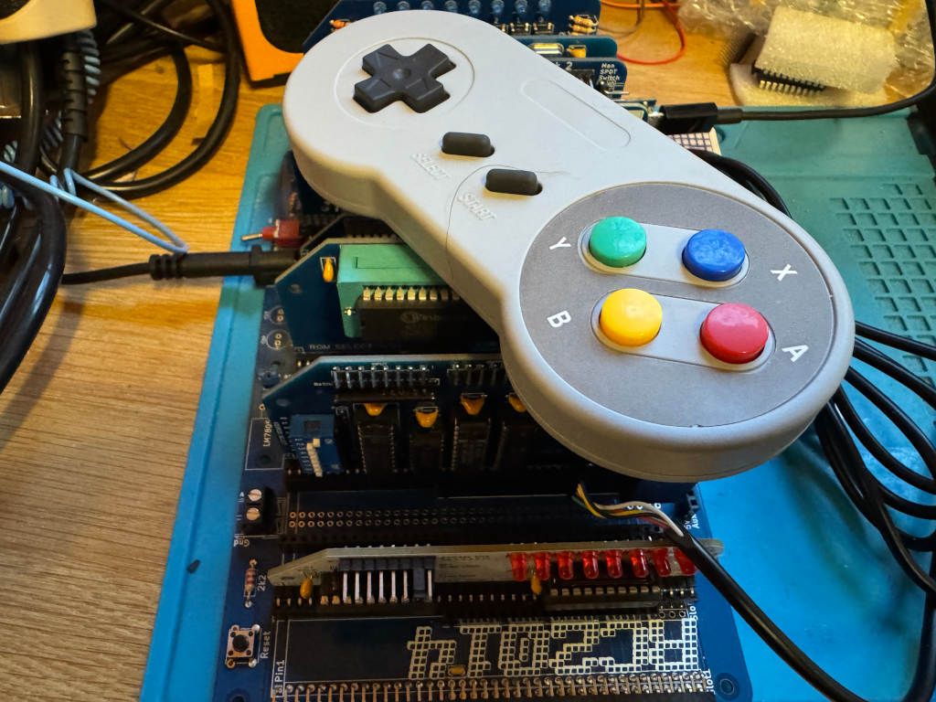
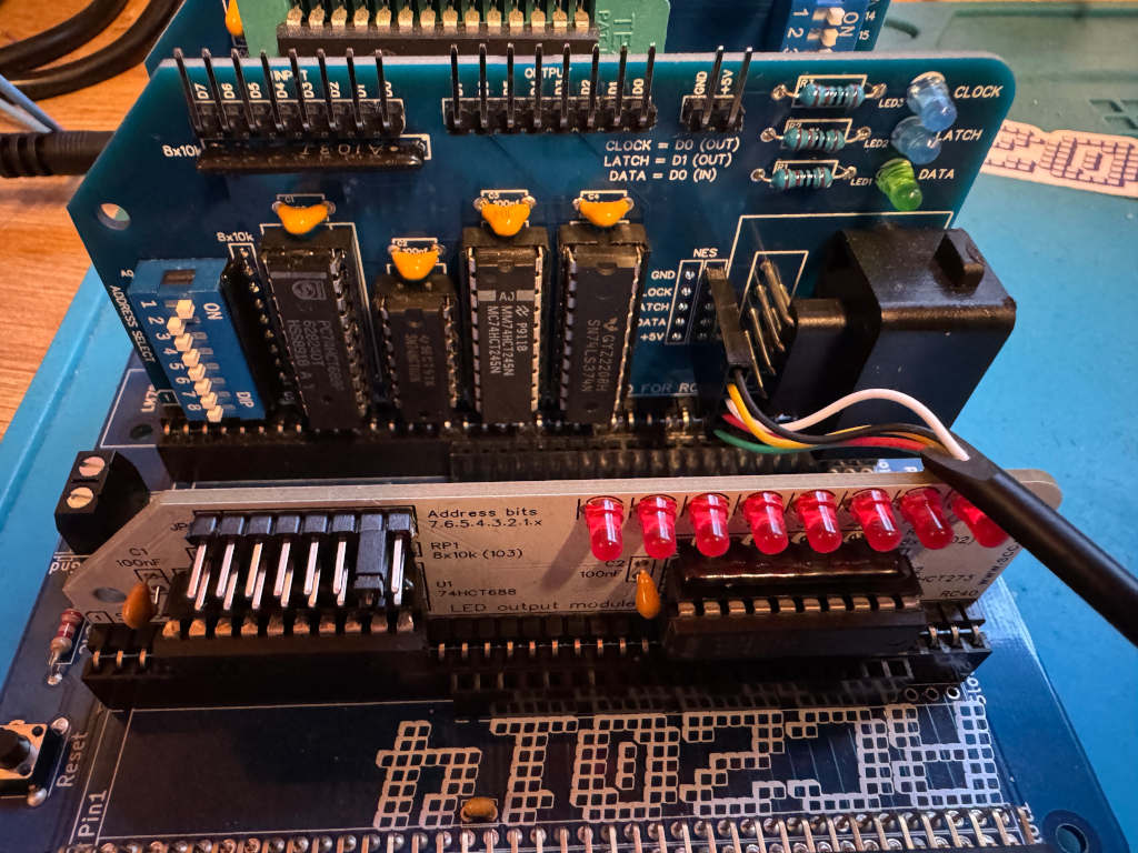
I wanted to see if my existing work could be easily extended to use a SNES controller, so I bought one on AliExpress. I also bought a SNES extension lead so I could cut it in half and add Dupont sockets to the wires. This means I could wire it directly to the RC2014 module I designed for the NES controller using one of the debug connectors I added to the PCB.
The SNES controller uses a different connector, but the pins work in the same way. This diagram shows the 5 pins we are interested in, and how we need to wire them up to the RC2014 NES controller module.
Writing a reusable Z80 routine
As there are two bytes being returned, I can’t just call my get_buttons routine. This will toggle the Latch twice, so I will never get the extra buttons.
Instead, I have to toggle Latch one at the start of the routine, and call a cut down version of the original get_buttons routine that reads the 8 bits twice. The first byte returned will be the original NES buttons. The second byte will be the extra buttons on the SNES controller. Instead of returning a single byte in register a, I will instead use register pair de. Register d will hold the NES button data, and register e will hold the SNES button data.
; SNESController.inc
; Definitions and subroutine to read SNES controller button states
; Robert Price - 1st November 2025


; The Z80 port address to use for the controller interface.
NES_PORT    EQU $01

; The bit masks for the controller interface lines.
CLOCK   EQU $01
LATCH   EQU $02
DATA    EQU $01


; subroutine to read the NES controller button states.
; returns the button states in DE registers.
; register D contains the high byte, and register E the low byte.
; All other registers are preserved.
; The high byte is like the NES controller, low has the extra SNES buttons.
get_buttons:
        push af           ; save af registers
        push bc           ; save bc registers

; pulse the LATCH line low to high and back to low again.
        xor a               ; set a to 0
        out (NES_PORT), a
        ld a, LATCH
        out (NES_PORT), a
        xor a               ; set a to 0
        out (NES_PORT), a

        call .get_buttons
        ld d, a             ; store the button states in register d
        call .get_buttons
        ld e, a             ; store the button states in register e

        pop bc              ; restore bc registers
        pop af              ; restore af registers

        ret                 ; return to caller with button states in a


.get_buttons:
; setup the loop counter to read 8 buttons.
        ld b, 8             ; 8 buttons to read.

; now we rebuild the byte into register c. As we are setting all 8 bits,
; we don't need to worry about clearing c first.
.loop:
; read the controller button states
        in a, (NES_PORT)    ; read the DATA line

; move the DATA bit into register c to rebuild the send byte
        srl a               ; shift right to get the DATA bit into carry
        rr c                ; rotate carry into bit 7 of c

; pulse the CLOCK line to read the next button.
        ld a, CLOCK
        out (NES_PORT), a
        xor a               ; set a to 0
        out (NES_PORT), a

; loop to read all buttons.
        djnz .loop

; return the button states in register a
        ld a, c             ; put the final button states in a
        ret
Using the new Z80 routine
To test the new routine, I can use LEDs as before. I have two modules that can display an 8-bit value using LEDs. A RC2014 Digital IO module at IO address 0, and a SC134 module at IO address 2. I will display one returned byte on one of the modules, and the second returned byte on the other module. This can be run using SCM as before.
 ; A simple button reading program for the RC2014 Z80 computer running SCM
 ; this version outputs the SNES button states to a LED output
 ; Robert Price - 1st November 2025

        ORG $9000

; the Z80 port address to use for the LED output.
; This expects two Digital IO ports to be connected to the RC2014,
; one at IO address 0 for the high byte, and one at IO address 2 for the low byte.
LED_PORT_H  EQU $00
LED_PORT_L  EQU $02

main:
; get the button states from the SNES controller
        call get_buttons     ; call the get_buttons subroutine
        ld a, d              ; get the high byte button states
        cpl                  ; invert the bits in register a so pressed buttons are 1, and unpressed are 0
        out (LED_PORT_H), a  ; output the button states to the LED port

        ld a, e              ; get the low byte button states
        cpl                  ; invert the bits in register a so pressed buttons are 1, and unpressed are 0
        out (LED_PORT_L), a  ; output the button states to the LED port

        jr main              ; repeat forever

        INCLUDE "SNESController.inc"

        END
I’ve made good progress with my RetroChallenge to get an NES controller working on my RC2014 computer.
I wanted to be able to play a game with the controller. I had hoped to write my own, but with only a few days left, I didn’t think this was practical. Instead, I wondered about hacking an existing game.
While it’s not an RC2014, the Sinclair ZX Spectrum is also based on the Z80 processor. Colin Piggot makes a ZX Spectrum Bus Interface that allows RC2014 cards to be plugged into a Speccy.
As the RC2014 NES controller module can now be plugged into a Speccy, could I adapt one of my favourite games to work with it? Could Manic Miner be playable with an NES controller?
The first step was to try to disassemble Manic Miner to see how the existing Kempston joystick support worked. I was hoping it would be simple to just wire in NES controller support there.
The Kempston joystick interface works by using a Z80 in operation on port 31. I would need to fake this by calling a routine to read the NES controller and return data in the Kempston format.
The Kempston joysticker interface returns the following in a single byte.
Bit
Value
0
Right
1
Left
2
Down
3
Up
4
Fire
5
N/A
6
N/A
7
N/A
So, if the Fire button is being pressed, bit 4 will be 1.
I can modify the get_buttons routine I previously wrote to read the NES controller and return the data in this format.
To do this, before the pop bc instruction, I can add the following code.
; build the kempston joystick byte in register a
        xor a               ; clear a

.test_fire:
        bit NES_A_BTN, c
        jr nz, .test_up
        set 4, a
.test_up:
        bit NES_UP_BTN, c
        jr nz, .test_down
        set 3, a
.test_down:
        bit NES_DOWN_BTN, c
        jr nz, .test_left
        set 2, a
.test_left:
        bit NES_LEFT_BTN, c
        jr nz, .test_right
        set 1, a
.test_right:
        bit NES_RIGHT_BTN, c
        jr nz, .done
        set 0, a
.done:
        pop bc              ; restore bc registers
Here I am clearing the a register so all bits have a default value of 0. Next, I am testing the bits in the byte I built to store the values from the NES controller. If the bits are set in the NES byte, then I set the relevant bit in the Kempston byte.
Hacking Manic Miner
My original idea was to load Manic Miner into a Spectrum, then use a Multiface to poke my changes into memory. Although this would work, I decided it would take too long and would be harder to save my work.
Instead, I downloaded a clean .tap file of Manic Miner from World of Spectrum and loaded this into the ZEsarUX emulator. ZEsarUX will let me poke my changes into the game and save the results as an SNA file. I can use the SNA file on a DivMMC connected to my Spectrum to load the game. This means I can make sure the game is still working before saving my changes.
I needed to find a place to store my get_buttons routine in Manic Miner. Upon examining the disassembly, remnants of the source code from when Matthew Smith was writing the game are visible at 0x934c. This space is unused in the game, so it’s safe for me to put my code there.
; A simple button reading program for the RC2014 Z80 computer running SCM
; This will pretend to be a Kempston joystick interface, and return bits like that interface.
; Robert Price - 24th October 2025

        ORG $934c

; The Z80 port address to use for the controller interface.
NES_PORT    EQU $01

; The bit masks for the controller interface lines.
CLOCK   EQU $01
LATCH   EQU $02
DATA    EQU $01

NES_A_BTN      EQU $00
NES_UP_BTN     EQU $04
NES_DOWN_BTN   EQU $05
NES_LEFT_BTN   EQU $06
NES_RIGHT_BTN  EQU $07


; subroutine to read the NES controller button states.
; returns the button states in register a.
; all other registers are preserved.
get_buttons:
        push bc           ; save bc registers

; pulse the LATCH line low to high and back to low again.
        xor a               ; set a to 0
        out (NES_PORT), a
        ld a, LATCH
        out (NES_PORT), a
        xor a               ; set a to 0
        out (NES_PORT), a

; setup the loop counter to read 8 buttons.
        ld b, 8             ; 8 buttons to read. This will be decremented to 0.

; now we rebuild the byte into register c. As we are setting all 8 bits,
; we don't need to worry about clearing c first.
.loop:
; read the controller button states
        in a, (NES_PORT)    ; read the DATA line

; move the DATA bit into register c to rebuild the send byte
        srl a               ; shift right to get the DATA bit into carry
        rr c                ; rotate carry into bit 7 of c

; pulse the CLOCK line to read the next button.
        ld a, CLOCK
        out (NES_PORT), a
        xor a               ; set a to 0
        out (NES_PORT), a

; loop 8 times to read all buttons.
        djnz .loop

; build the kempston joystick byte in register a
        xor a               ; clear a

.test_fire:
        bit NES_A_BTN, c
        jr nz, .test_up
        set 4, a
.test_up:
        bit NES_UP_BTN, c
        jr nz, .test_down
        set 3, a
.test_down:
        bit NES_DOWN_BTN, c
        jr nz, .test_left
        set 2, a
.test_left:
        bit NES_LEFT_BTN, c
        jr nz, .test_right
        set 1, a
.test_right:
        bit NES_RIGHT_BTN, c
        jr nz, .done
        set 0, a
.done:
        pop bc              ; restore bc registers

        ret                 ; return to caller with button states in a
I compiled the code using the sjasmplus assembler on my Mac, and this gave me a 61-byte block of assembled code. Running this through hexdump gave me the following hex code to poke into memory.
9c4c  c5 af d3 01 3e 02 d3 01  af d3 01 06 08 db 01 cb
9c5c  3f cb 19 3e 01 d3 01 af  d3 01 10 f1 af cb 41 20
9c6c  02 cb e7 cb 61 20 02 cb  df cb 69 20 02 cb d7 cb
9c7c  71 20 02 cb cf cb 79 20  02 cb c7 c1 c9
I used the Hexadecimal Editor in the Debug Menu of ZEsarUX to input this.
Now I needed to call this when the Kempston joystick was being called from the game.
The first place this is done is at address 0x8878. This code checks if the fire button is being pressed in demo mode.
8878	LD A,($8459)	Pick up the Kempston joystick indicator from 8459
887B	OR A	        Is there a joystick connected?
887C	JR Z,$8884	Jump if not
887E	IN A,($1F)	Collect input from the joystick
In this case, I don’t need to check the joystick indicator, so all 4 instructions can be replaced with the following.
The NOP instructions tell the Z80 to do nothing. I am just using them to fill up the space that the 4 original instructions were using. The assembled code looks like this, and it was loaded using the hexadecimal editor.
8878 cd 4c 93 00 00 00 00 00
The next block of code looks for left or right being pressed at address 0x8C24
8C24	LD A,($8459)	Collect the Kempston joystick indicator from 8459
8C27	OR A	        Is the joystick connected?
8C28	JR Z,$8C34	Jump if not
8C2A	LD BC,$001F	Collect input from the joystick
8C2D	IN A,(C)
I can use the same code as before to drop in there, but I need an extra 3 NOP instructions to fill up the space. The replacement hex code looks like this.
8C24 cd 4c 93 00 00 00 00 00 00 00 00
There is similar code to check the fire button at address 0x8c6c. I can poke in the same hex code there.
8C6C cd 4c 93 00 00 00 00 00 00 00 00
Finally, there is a routine at 0x9337 that checks if the fire button is being pressed. This is a shorter version like the code at 0x8878, so I can poke in the same code there.
9337 cd 4c 93 00 00 00 00 00
I can now save a snapshot of the game. I do this using the Snapshot option in ZEsarUX and making sure I use a .SNA file extension. I called my file MMNES.SNA. It’s available to download for anyone following along.
Copying this to an SD card and placing it in the DivMMC allowed me to load the modified game on my Spectrum.
Conclusion
While I hadn’t planned to hack a Spectrum game as part of the RetroChallenge this year, it’s turned out to be a great diversion and learning experience. It’s still using the code and hardware developed on the RC2014.
The joypad works well, and although it is using a little more CPU time, it’s not noticeable when playing the game. It doesn’t have the nostalgia value of using the Spectrum’s rubber keys, but it is responsive and comfortable to use.
In previous posts, I’ve covered how to read an NES controller from an RC2014 computer, and also how to use an 8×8 LED matrix. I now want to combine these and use the NES controller to move a pixel on the LED matrix.
The first thing we want to do is to draw a pixel in the top left corner of the LED matrix. To do this, I’ll use register b for the Row data and register c for the Column data. We need to set a single bit in each because we only want a single pixel lit.
        ORG $9000

ROW     EQU 0
COLUMN  EQU 2

setup:
        ld b, 0b00000001  ; Row bit for the pixel
        ld c, 0b10000000  ; Column bit for the pixel

main:

.draw_pixel:
        xor a             ; clear a
        out (COLUMN), a   ; clear the columns
        ld a, b           ; get the current row bit
        out (ROW), a      ; select the row
        ld a, c           ; get the column data for this row
        out (COLUMN), a   ; output the column data

        jr main           ; repeat forever

        END
Now that we have a pixel, we need to read the NES controller and react to movement on the joypad.
We can use Z80 rlc and rrc operations to move the single bit to the left or right in the Row and Column registers. If we reach the end of the byte, the bit will roll over to the other end of the byte.
To test which button is being pressed, we can use a bit operation. If the button isn’t being pressed, we can jump ahead to test the next button.
In our main loop, we can add the following.
UP_BTN   EQU $04
DOWN_BTN EQU $05
LEFT_BTN EQU $06
RIGHT_BTN EQU $07

main:
        call get_buttons   ; Get NES controller button states in A

.test_left:
        bit LEFT_BTN, a
        jr nz, .test_right
        rlc c
.test_right:
        bit RIGHT_BTN, a
        jr nz, .test_up
        rrc c
.test_up:
        bit UP_BTN, a
        jr nz, .test_down
        rrc b
.test_down:
        bit DOWN_BTN, a
        jr nz, .draw_pixel
        rlc b

.draw_pixel:
At the moment, this is executing far too fast, so we end up with an entire row or column being lit. We need to add a delay. We can write a very simple Z80 routine to just loop X times as a simple delay.
delay:
ld de, 50000
.delay_loop:
dec de
ld a, d
or e
jr nz, .delay_loop
ret
The final working code
Putting this all together, we end up with the following code…
; A simple program to move a pixel on an 8x8 LED matrix
; connected to the RC2014 Z80 computer.
; Robert Price - 19th October 2025
ORG $9000
ROW EQU 0
COLUMN EQU 2
UP_BTN EQU $04
DOWN_BTN EQU $05
LEFT_BTN EQU $06
RIGHT_BTN EQU $07
setup:
ld b, 0b00000001 ; Row bit for the pixel
ld c, 0b10000000 ; Column bit for the pixel
main:
call get_buttons ; Get NES controller button states in A
.test_left:
bit LEFT_BTN, a
jr nz, .test_right
rlc c
.test_right:
bit RIGHT_BTN, a
jr nz, .test_up
rrc c
.test_up:
bit UP_BTN, a
jr nz, .test_down
rrc b
.test_down:
bit DOWN_BTN, a
jr nz, .draw_pixel
rlc b
.draw_pixel:
xor a ; clear a
out (COLUMN), a ; clear the columns
ld a, b ; get the current row bit
out (ROW), a ; select the row
ld a, c ; get the column data for this row
out (COLUMN), a ; output the column data
call delay ; small delay to make movement visible
jr main ; repeat forever
delay:
ld de, 50000
.delay_loop:
dec de
ld a, d
or e
jr nz, .delay_loop
ret
        INCLUDE "NESController.inc"

        END
As part of the 2025 RetroChallenge I’ve been developing an NES controller module for the RC2014 computer.
Up until now, I’ve just been outputting to a terminal. However, I’d like to use something a bit more visual on the RC2014. I’ve decided to use Peacock Media’s 8×8 LED matrix module for this.
The module works by outputting an 8-bit value to one IO port for the row and another 8-bit value to another IO port for the column. These describe which LEDs should be enabled. Each bit in the byte refers to either a row or a column.
The default IO port for the row is 0, and the default IO port for the column is 2.
If I want the top left corner to light, I need to set bit 8 of the column and bit 1 of the row.
If you have the SCM (Small Computer Monitor) program running on an RC2014, you can quickly test it out using the following.
o 0 1
o 2 80
This sets the row to hexadecimal 1, which in binary is 00000001, and the column to hexadecimal 80 which in binary is 1000000.
A smiley face in BASIC
In the documentation for the 8×8 module, Shelia Dixon gives us an example BASIC program to draw a smiley face.
This works by rapidly updating the pixels rather than keeping them permanently on. Repeated fast enough, persistence of vision makes the LEDs appear to be on constantly.
10 FOR I=0 TO 7
20 READ R,C
30 OUT 2,0 : OUT 0,R : OUT 2,C
40 NEXT I
50 RESTORE
60 GOTO 10
1000 DATA 1,60, 2,66, 4,169, 8,169
1010 DATA 16,133, 32,185, 64,66, 128,60
A smiley face in Z80 assembly language
I wanted to convert the BASIC program to Z80 assembly language to help me better understand how this works.
I take a similar approach to the BASIC program. I iterate over a loop 8 times to represent the current Row. I keep this counter in register b. In register c, I keep the current bit the row is pointing to. In each iteration, I read a byte of data from memory that represents the Column. The position in memory is pointed to by register pair hl. Once the data has been output, I then shift the value in register c to the right so it points to the next row.
The final code looks like this.
; A simple program to display a smiley face on an 8x8 LED matrix
; connected to the RC2014 Z80 computer.
; Robert Price - 19th October 2025
;
; Based on the original BASIC example by Shiela Dixon
        ORG $9000

ROW     EQU 0
COLUMN  EQU 2

main:
        ld b, 8           ; 8 rows to display
        ld c, 0b10000000  ; start with bit 7 set for row 8
        ld hl, data       ; point to the smiley data
.loop:
        xor a             ; clear a
        out (COLUMN), a   ; clear the columns
        ld a, c           ; get the current row bit
        out (ROW), a      ; select the row
        ld a, (hl)        ; get the column data for this row
        out (COLUMN), a   ; output the column data
        inc hl            ; point to next row data
        srl c             ; shift to next row bit
        djnz .loop        ; loop for all 8 rows

        jr main           ; repeat forever

data:
        db 0b00111100     ; 60
        db 0b01000010     ; 66
        db 0b10111001     ; 185
        db 0b10000101     ; 133
        db 0b10101001     ; 169
        db 0b10101001     ; 169
        db 0b01000010     ; 66
        db 0b00111100     ; 60

        END
I wanted to write a reusable Z80 assembly language subroutine to read the NES controller and return the status of the buttons in a register.
The principle is the same as my previous posts in that I have to pulse the Latch and Clock lines, and read data 1 bit at a time from the Data line. However, this time I want to store all 8 returned bits in a single byte that I can return in a register.
I had some feedback from Jon Jones on Bluesky who suggested I could optimise my previous code by replacing the ld a,0 instruction with xor a. This is a byte smaller, and is quite a neat trick as a value exclusive or’d with itself will always be 0.
I have also been learning more about how shifting and rotating works on the Z80. When I read my bit from the data line, if I use a slr a instruction, it will push the bit that has just been read onto the carry flag. I can then use rr c to move the contents of register c one to the right and fill bit 7 with the contents of the carry flag. Doing this 8 times will fill the c register with all the values I need.
The finished subroutine looks like this.
; NESController.inc
; Definitions and subroutine to read NES controller button states
; Robert Price - 19th October 2025


; The Z80 port address to use for the controller interface.
NES_PORT    EQU $01

; The bit masks for the controller interface lines.
CLOCK   EQU $01
LATCH   EQU $02
DATA    EQU $01


; subroutine to read the NES controller button states.
; returns the button states in register a.
; all other registers are preserved.
get_buttons:
        push bc           ; save bc registers

; pulse the LATCH line low to high and back to low again.
        xor a               ; set a to 0
        out (NES_PORT), a
        ld a, LATCH
        out (NES_PORT), a
        xor a               ; set a to 0
        out (NES_PORT), a

; setup the loop counter to read 8 buttons.
        ld b, 8             ; 8 buttons to read. This will be decremented to 0.

; now we rebuild the byte into register c. As we are setting all 8 bits,
; we don't need to worry about clearing c first.
.loop:
; read the controller button states
        in a, (NES_PORT)    ; read the DATA line

; move the DATA bit into register c to rebuild the send byte
        srl a               ; shift right to get the DATA bit into carry
        rr c                ; rotate carry into bit 7 of c

; pulse the CLOCK line to read the next button.
        ld a, CLOCK
        out (NES_PORT), a
        xor a               ; set a to 0
        out (NES_PORT), a

; loop 8 times to read all buttons.
        djnz .loop

; return the button states in register a
        ld a, c             ; put the final button states in a

        pop bc              ; restore bc registers

        ret                 ; return to caller with button states in a
Testing the subroutine
To test the new subroutine I made use of the SC134 LED output card I was kindly given at RC2014 Assembly. The standard RC2014 Digital IO card will also work. I have assigned this to IO address 2.
The code simply reads the NES controller, inverts the bits using the cpl instruction, outputs the value to the LEDs, and loops.
I need to use the cpl instruction as the NES controller returns a pressed button as 0. If I didn’t do this, the LEDs would be on apart from any button being pressed. cpl inverts all the bits in the a register so any button being pressed is now lit.
; the Z80 port address to use for the LED output.
LED_PORT    EQU $02

main:
; get the button states from the NES controller
        call get_buttons     ; call the get_buttons subroutine
        cpl                  ; invert the bits in register a so pressed buttons are 1, and unpressed are 0
        out (LED_PORT), a    ; output the button states to the LED port
        jr main              ; repeat forever
In my last post, I wrote about using MS-Basic on my RC2014 to bit-bang an NES controller. In this post, I want to use Z80 assembly language to do the same. I want to be able to press a button on the controller and have its name printed on the serial terminal.
The first thing we need to do is set up a few things.
The code will need to run at 0x9000, so an ORG statement will tell the assembler to build the code to run from there.
ORG $9000
The NES controller module will be located at the Z80 IO port 1.
PORT EQU $01
The Clock bit is 1, the Latch bit is 2, and the Data bit is 1.
CLOCK   EQU $01
LATCH   EQU $02
DATA    EQU $01
I’ll be using Stephen Cousins’ SCM on the RC2014. The SCM API provides a routine to print a string, so I’ll be using that later on. This is API call 0x06.
OUTPUT_LINE EQU $06
The first thing the code will need to do is to pulse the Latch line low, high, low. This will capture the current state of the buttons being pressed on the NES controller.
start:
        ld a, 0
        out (PORT), a
        ld a, LATCH
        out (PORT), a
        ld a, 0
        out (PORT), a
Now we need to loop 8 times to capture each of the 8 bits the NES controller is going to be sending us.
        ld b, 8
loop:
        djnz loop
Inside the loop, we first need to read the Data line to get the current bit. We mask out all but the Data bit and then see if it is 0 or not. If it’s not zero, skip the next block of code.
        in a, (PORT)

        and DATA
        jr nz, .skip
If a button is being pressed, we need to look up the name of the button in a lookup table and print it out using the SCM API. To do this, we get the current iteration minus 1 and store it in the HL register. As this is a 16 bit register, we need to set the L register to the iteration value, and H to 0. We add this value to the address of the lookup table to get the address of the string to print. We then pass this to the SCM API.
        ld de, lookuptable  ; point to the lookup table
        ld a, b             ; put the current iteration from b into a
        dec a               ; delete 1 to make it zero based
        ld l, a             ; place the interation in l
        ld h, 0             ; zero h, hl should now be value of the iteration
        add hl, hl          ; multiply by 2 (size of address)
        add hl, de          ; add to base address of table
        ld e, (hl)          ; get low byte of string address to use
        inc hl              ; point to high byte
        ld d, (hl)          ; get high byte of string address
        ld c, OUTPUT_LINE   ; SCM output line
        push bc             ; save the bc registers to the stack
        rst $30             ; Call SCM API
        pop bc              ; restore the bc registers from the stack
lookuptable:
        dw right_txt
        dw left_txt
        dw down_txt
        dw up_txt
        dw start_txt
        dw select_txt
        dw b_txt
        dw a_txt

a_txt:      db "A",5,0
b_txt:      db "B",5,0
select_txt: db "Select",5,0
start_txt:  db "Start",5,0
up_txt:     db "Up",5,0
down_txt:   db "Down",5,0
left_txt:   db "Left",5,0
right_txt:  db "Right",5,0
Next, we pulse the CLOCK line high to low before we end the loop.
.skip:
        ld a, CLOCK
        out (PORT), a
        ld a, 0
        out (PORT), a
Finally, we loop back to the very start of the program.
jr start
The complete Z80 assembly language program
Here’s the code as a single program that can be assembled using the sjasmplus assembler.
 ; A simple button reading program for the RC2014 Z80 computer running SCM
 ; Robert Price - 15th October 2025

        ORG $9000

; The Z80 port address to use for the controller interface.
PORT    EQU $01

; The bit masks for the controller interface lines.
CLOCK   EQU $01
LATCH   EQU $02
DATA    EQU $01

; The SCM API value to output a line.
OUTPUT_LINE EQU $06

start:
; pulse the LATCH line low to high and back to low again.
        ld a, 0
        out (PORT), a
        ld a, LATCH
        out (PORT), a
        ld a, 0
        out (PORT), a

; setup the loop counter to read 8 buttons.
        ld b, 8             ; 8 buttons to read. This will be decremented to 0.
loop:
; read the controller button states
        in a, (PORT)        ; read the DATA line

        and DATA            ; mask out all but DATA bit
        jr nz, .skip        ; skip if a button was not pressed

; print out the button pressed using a lookup table.
        ld de, lookuptable  ; point to the lookup table
        ld a, b             ; put the current iteration from b into a
        dec a               ; delete 1 to make it zero based
        ld l, a             ; place the interation in l
        ld h, 0             ; zero h, hl should now be value of the iteration
        add hl, hl          ; multiply by 2 (size of address)
        add hl, de          ; add to base address of table
        ld e, (hl)          ; get low byte of string address to use
        inc hl              ; point to high byte
        ld d, (hl)          ; get high byte of string address
        ld c, OUTPUT_LINE   ; SCM output line
        push bc             ; save the bc registers to the stack
        rst $30             ; Call SCM API
        pop bc              ; restore the bc registers from the stack

.skip:
; pulse the CLOCK line to read the next button.
        ld a, CLOCK
        out (PORT), a
        ld a, 0
        out (PORT), a

; loop 8 times to read all buttons.
        djnz loop

; forever loop to read buttons again.
        jr start


; the lookup table stores the addresses of the text strings for each button.
lookuptable:
        dw right_txt
        dw left_txt
        dw down_txt
        dw up_txt
        dw start_txt
        dw select_txt
        dw b_txt
        dw a_txt

; The text strings to print for each button.
; each string is terminated with a CR (5) and a null (0).
a_txt:      db "A",5,0
b_txt:      db "B",5,0
select_txt: db "Select",5,0
start_txt:  db "Start",5,0
up_txt:     db "Up",5,0
down_txt:   db "Down",5,0
left_txt:   db "Left",5,0
right_txt:  db "Right",5,0
Once assembled, I convert it to Intel Hex using z88dk-appmake and send it to my RC2014 running SCM. It is then executed using g 9000 .
It is very fast code, so even the slightest tap of a button will register multiple times.
Cookie Consent
We use cookies to improve your experience on our site. By using our site, you consent to cookies.
Websites store cookies to enhance functionality and personalise your experience. You can manage your preferences, but blocking some cookies may impact site performance and services.
Essential cookies enable basic functions and are necessary for the proper function of the website.
Name
Description
Duration
Cookie Preferences
This cookie is used to store the user's cookie consent preferences.
30 days
Statistics cookies collect information anonymously. This information helps us understand how visitors use our website.
Google Analytics is a powerful tool that tracks and analyzes website traffic for informed marketing decisions.
Contains information related to marketing campaigns of the user. These are shared with Google AdWords / Google Ads when the Google Ads and Google Analytics accounts are linked together.
90 days
__utma
ID used to identify users and sessions
2 years after last activity
__utmt
Used to monitor number of Google Analytics server requests
10 minutes
__utmb
Used to distinguish new sessions and visits. This cookie is set when the GA.js javascript library is loaded and there is no existing __utmb cookie. The cookie is updated every time data is sent to the Google Analytics server.
30 minutes after last activity
__utmc
Used only with old Urchin versions of Google Analytics and not with GA.js. Was used to distinguish between new sessions and visits at the end of a session.
End of session (browser)
__utmz
Contains information about the traffic source or campaign that directed user to the website. The cookie is set when the GA.js javascript is loaded and updated when data is sent to the Google Anaytics server
6 months after last activity
__utmv
Contains custom information set by the web developer via the _setCustomVar method in Google Analytics. This cookie is updated every time new data is sent to the Google Analytics server.
2 years after last activity
__utmx
Used to determine whether a user is included in an A / B or Multivariate test.
18 months
_ga
ID used to identify users
2 years
_gali
Used by Google Analytics to determine which links on a page are being clicked
30 seconds
_ga_
ID used to identify users
2 years
_gid
ID used to identify users for 24 hours after last activity
24 hours
_gat
Used to monitor number of Google Analytics server requests when using Google Tag Manager
1 minute
Marketing cookies are used to follow visitors to websites. The intention is to show ads that are relevant and engaging to the individual user.
A video-sharing platform for users to upload, view, and share videos across various genres and topics.
Registers a unique ID on mobile devices to enable tracking based on geographical GPS location.
1 day
VISITOR_INFO1_LIVE
Tries to estimate the users' bandwidth on pages with integrated YouTube videos. Also used for marketing
179 days
PREF
This cookie stores your preferences and other information, in particular preferred language, how many search results you wish to be shown on your page, and whether or not you wish to have Google’s SafeSearch filter turned on.
10 years from set/ update
YSC
Registers a unique ID to keep statistics of what videos from YouTube the user has seen.
Session
DEVICE_INFO
Used to detect if the visitor has accepted the marketing category in the cookie banner. This cookie is necessary for GDPR-compliance of the website.
179 days
LOGIN_INFO
This cookie is used to play YouTube videos embedded on the website.
2 years
VISITOR_PRIVACY_METADATA
Youtube visitor privacy metadata cookie
180 days
You can find more information in our Cookie Policy and .