In previous posts, I’ve been able to read the temperature and humidity using a BME280 sensor attached to my RC2014 computer. The BME280 has one other reading it can provide, and that is atmospheric pressure.
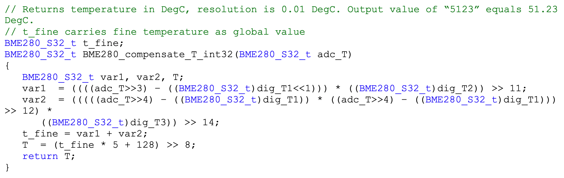
As with the temperature and humidity, I need to calculate the value using the calibration data stored in the BME280. I also need the value of t_fine I stored when calculating the temperature. My previous post showed how to get these values. The BME280 datasheet gives me the algorithm and example code to calculate the air pressure.
The BME280 can also provide readings for humidity and atmospheric pressure. In this post, I’m going to look at reading humidity.
The BME280 provides the humidity value as a 24bit integer. I can use the read24 function I defined in my last post to read this value from the BME280. However, I can’t use it directly. Like the temperature reading, I have to do some calculations using the calibration data from the BME280. Thankfully, the BME280 datasheet gives me an algorithm to do this on page 25, so I just need to tweak this to drop in the relevant values.
That was really simple because most of the hard work had already been done in my previous post. The readHumidity function looks complex, but it’s just the example code from the datasheet tweaked to use my variables.
In my previous posts, I’ve shown how to read the ID value from a BME280 sensor using an RC2014 computer. That’s not very useful in itself, but it is a good building block for getting practical information from the sensor. In this post, I’m going to read the current temperature.
The temperature isn’t returned as a sensible, human-understandable value directly from the sensor. It needs to be calculated using calibration data that the BME280 also supplies. The BME280 datasheet gives us an algorithm to do this.
I also need to tell the BME280 to continually sense; otherwise, it is in sleep mode.
The BME280 is a very well-known sensor, and there are some libraries written for other systems that I can use to verify my work. Adafruit has a BME280 library for the Arduino that is written in C++. I am going to use some of the code from the Adafruit library where possible.
Writing and reading data
My previous post had a transfer routine to handle the bit-banging of SPI data, so I am going to build upon this.
The first routine we need is one to send and receive data of different lengths. I pass in address locations and lengths. The routine will then bit-bang that amount of data.
void write_then_read(const uint8_t *write_data, uint8_t write_length, uint8_t *read_data, uint8_t read_length) {
    // Deselect the BME280 to ensure it's not selected before starting communication.
    io_spi = SELECT | CLK | MOSI;

    // Write data
    for (uint8_t i = 0; i < write_length; i++) {
        transfer(write_data[i]);
    }

    // Read data
    for (uint8_t i = 0; i < read_length; i++) {
        read_data[i] = transfer(0x00); // Send dummy byte to read
    }

    // Deselect the BME280 after communication is done.
    io_spi = SELECT | CLK | MOSI;
}
I need to be able to read in 8 bit, 16 bit, and 24 bit values in little-endian format, both signed and unsigned, as well as to be able to write an 8 bit value. These utility routines can help with that.
The BME280 has numerous registers we can read and write to. The ID we retrieve in the previous blog post uses register 0xd0. Adafruit has defined all of these in their library, so I will reuse their code for this.
The BME280 doesn’t do much unless it’s told to. So we need a routine to turn it on and get it sampling data. There are various configurations defined in the BME280 documentation, but I’m going to lift these values from the Adafruit library, as they have done the hard work of turning them into enum values already.
To set the sampling rate, I need to perform several operations. I first put the BME280 to sleep. This allows me to safely update the configuration and control registers.
void setSampling(enum sensor_mode mode, enum sensor_filter filter, enum standby_duration duration) {
    // Set the sensor to sleep mode before changing settings
    write8(BME280_REGISTER_CONTROL, MODE_SLEEP);

    // Set the humidity oversampling to x1 (0b001)
    write8(BME280_REGISTER_CONTROLHUMID, 0b001);

    // Set the filter and standby duration in the config register
    uint8_t config = (duration << 5) | (filter << 2);
    write8(BME280_REGISTER_CONFIG, config);

    // Set the temperature and pressure oversampling to x1 (0b001)
    // and the mode
    uint8_t control = (0b001 << 5) | (0b001 << 2) | mode;
    write8(BME280_REGISTER_CONTROL, control);
}
Reading the calibration coefficients
I mentioned earlier the need to use calibration data to calculate the temperature. We need to get these values and store them.
typedef struct {
  uint16_t dig_T1; ///< temperature compensation value
  int16_t dig_T2;  ///< temperature compensation value
  int16_t dig_T3;  ///< temperature compensation value

  uint16_t dig_P1; ///< pressure compensation value
  int16_t dig_P2;  ///< pressure compensation value
  int16_t dig_P3;  ///< pressure compensation value
  int16_t dig_P4;  ///< pressure compensation value
  int16_t dig_P5;  ///< pressure compensation value
  int16_t dig_P6;  ///< pressure compensation value
  int16_t dig_P7;  ///< pressure compensation value
  int16_t dig_P8;  ///< pressure compensation value
  int16_t dig_P9;  ///< pressure compensation value

  uint8_t dig_H1; ///< humidity compensation value
  int16_t dig_H2; ///< humidity compensation value
  uint8_t dig_H3; ///< humidity compensation value
  int16_t dig_H4; ///< humidity compensation value
  int16_t dig_H5; ///< humidity compensation value
  int8_t dig_H6;  ///< humidity compensation value
} bme280_calib_data;

bme280_calib_data _bme280_calib;
The calibration data is a mix of signed and unsigned integers of various lengths. I can use the various read functions I defined earlier to read and save these.
The example code given in the BME280 datasheet returned the temperature as an integer, but for ease of use, I will want to use a floating-point value. This is simply the value from the datasheet divided by 100 to give us a value in Celsius. This routine makes extensive use of the calibration data from the BME280.
I have enough code to be able to read the temperature from the BME280, so it’s time to put it all together.
The first thing I need to do is reset the BME280. I can do this by writing to the soft reset register. Secondly, I turn on the BME280 and get it sampling. Next, I read the calibration data. Finally, in a loop, I can continually read the temperature and display it to my serial terminal.
int main(void) {
    write8(BME280_REGISTER_SOFTRESET, 0xB6);

    setSampling(MODE_NORMAL, FILTER_OFF, SAMPLING_X16);

    readCoefficients();

    while(1) {
      float temperature = readTemperature();
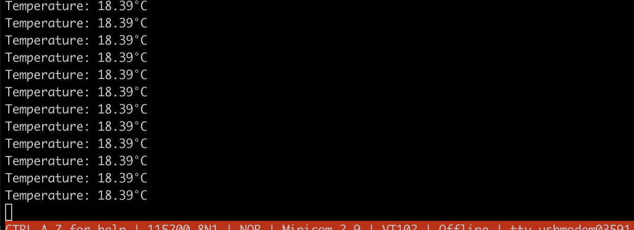
      printf("Temperature: %.2f°C\n", temperature);
    }
}
Compiling the code
Because I am using floating-point numbers, I need to include the maths library when compiling. I do this using the -lm flag.
The printf command doesn’t handle floating-point numbers by default, so I also need to enable this. This is done using a C pragma.
#pragma printf %f
When I compile the application using z88dk zcc, my command line looks like this.
It was very satisfying to see real temperatures on screen when I ran the code. The thermostat in my room was set to 18C, so this seems to be working really well.
In my previous post, I showed how to read the ID register on the BME280 by bit-banging the SPI protocol using Z80 assembly language. I want to be able to read the temperature using the BME280, but this requires the use of floating-point maths to convert the values returned from the device to a value in degrees Celsius. I think this would be a bit too complex to do using Z80 assembly language, so I plan to switch to using C instead.
I have previously written about using the z88dk C compiler with an RC2014, so I won’t fully go over this again. I will rewrite the previous assembly language code to get the ID of the BME280 device and display it on the LEDs.
Pragmas
I need to set a couple of pragma’s in the C code to tell the compiler where to assemble the code and where to set the stack pointer. The assembly language program ran from address 0x9000, so I will do the same here. I will also set the stack pointer to 0xFC00.
To use the Z80’s IO ports from C, I need to use a special function register. The C compiler z88dk uses has a special instruction called __sfr __at that declares a variable at a specific IO port. This variable can then be read from or assigned, and this maps to Z80 in and out instructions. I’m going to be using IO port 0x01 again.
Sending and receiving a byte of data takes place in parallel, so I’m going to create a C function that takes a byte as a parameter and also returns a byte.
First, I need to include stdint.h to get the required data type of uint8_t. I also need to define the bit masks for MOSI, MISO, CLK, and SELECT.
// Send a byte and receive a byte from the BME280 over SPI.
uint8_t transfer(uint8_t value) {
    uint8_t received_value = 0;
    for (int i = 0; i < 8; i++) {
        // Set the MOSI line based on the current bit of the value to send,
        // then det the CLK line low.
        if (value & 0x80) {
            io_spi = 0 &~SELECT &~CLK | MOSI; // Set MOSI high and CLK low.
        } else {
            io_spi = 0 &~SELECT &~CLK; // Set MOSI low and CLK low.
        }

        // Read the MISO line to get the received bit.
        uint8_t miso = io_spi & MISO; // Read MISO

        // Shift the received value left and add the new bit.
        received_value = (received_value << 1) | (miso ? 1 : 0);

        // Pulse the clock line high.
        if (value & 0x80) {
            io_spi = 0 &~SELECT | CLK | MOSI; // Set MOSI high and CLK high.
        } else {
            io_spi = 0 &~SELECT | CLK; // Set MOSI low and CLK high.
        }

        // Prepare for the next bit by shifting the value to send left
        value <<= 1;
    }
    return received_value;
}
Reading the ID byte and displaying the result
Now I have a function that can send and receive a byte; I can request the ID byte.
Firstly, I need to make sure the device isn’t selected. Next, I need to request the ID by sending the command 0xD0, then read the returned byte. I need to send a dummy value when reading the returned byte, so I will use 0x00 in this case. Finally, I deselect the BME280 and show the values on the LEDs, as with the assembly language version.
int main(void) {
    io_spi = SELECT | CLK | MOSI; // Deselect the BME280
    transfer(0xD0);               // send the address for the ID register.
    uint8_t id = transfer(0x00);  // Read the ID register.
    io_spi = SELECT | CLK | MOSI; // Deselect the BME280.

    io_spi = id;                  // display the ID value on the output port
    return 0;
}
I previously controlled a MAX7219 LED matrix over SPI from my RC2014 computer. Now I want to try another SPI device, the BM280 environmental sensor from Bosch. The code in this article builds on the previous work, so take a moment to read it if you haven’t already.
The BME280 can read temperature, pressure, and humidity. It is a 3.3V device, so I will need a voltage level converter to use it with a 5V RC2014.
The SPI communication will also need to be two-way, as I will need to tell the sensor what values to send me.
I used the following parts (note: Amazon affiliate links)
The regulator allowed me to generate a 3.3v power supply from the RC2014’s 5v supply. I was then able to use this on the low-voltage side of the level shifter to allow the signals to convert between 5v and 3.3v.
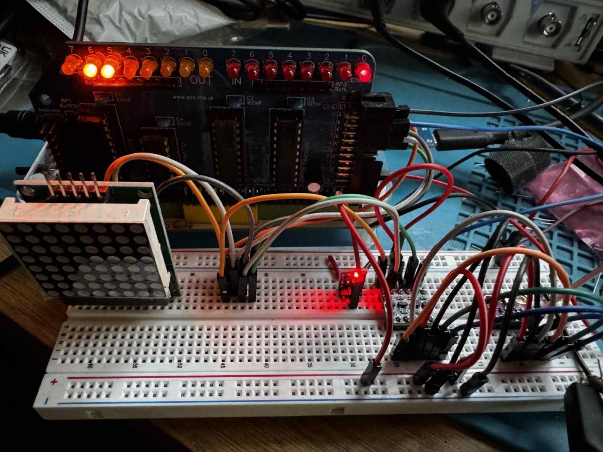
As before, I am using the SC129 Digital IO module on my RC2014 to bit-bang the SPI protocol. This is wired up via the level shifters and 3.3V regulator as follows…
SC129
BME280
GND
GND
5V
3.3V (via 3.3 regulator)
OUT D0
SDA / SDI (via level shifter)
OUT D1
SCL / SCK (via level shifter)
OUT D3
CSB (via level shifter)
IN D0
SDO (via level shifter)
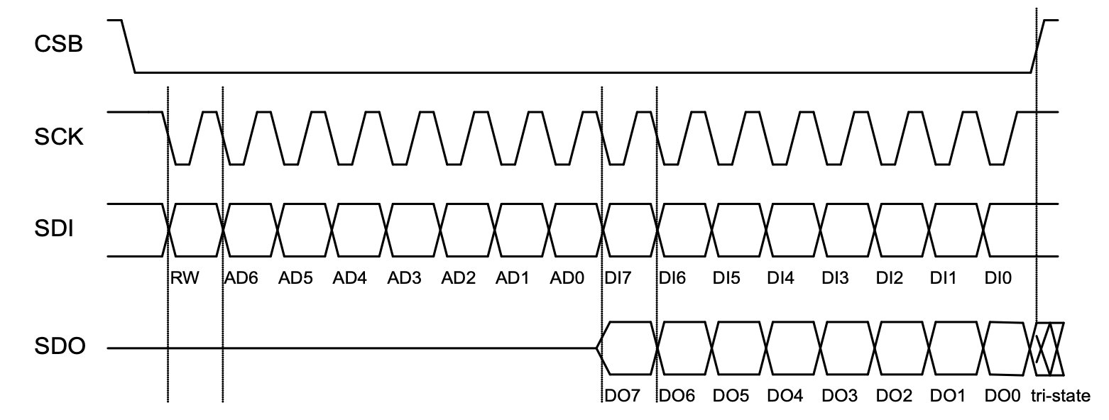
The BME280 gives us the following timing diagram for SPI communication.
Looking at the timing diagram, we can see that before we start any communication, the SCL / SCK and CSB lines both need to be high. We can use a subroutine to do this.
deselect_bme280:
    ld a, 0 | SELECT | CLK | MOSI
    out (OUTPUT_PORT),a
    ret
Sending and receiving take place on the transition of the SCK line from high to low.
This code is similar to the code for the LED matrix in my earlier post. I have added some additional code to handle the input. This reads the bit, rotates it right into the carry flag, then rotates that value into the E register. By the end of the routine, the byte in register D will have been sent, and the byte returned will be in register E.
send_receive_byte:
    push bc
    ld b, 8
    ld a, 0 &~SELECT &~CLK | MOSI
    rra
    ld c, a
.transmit_bme280_bit:
    ld a, c
    rl d
    rla
    out (OUTPUT_PORT), a.  ; CLK low
    in a, (INPUT_PORT)
    rra
    rl e
    ld a, c
    or a, CLK
    out (OUTPUT_PORT), a   ; CLK high
    djnz .transmit_bme280_bit
    pop bc
    ret
To test that this is working, we can send the value 0xD0 to the BME280. It should send back the value 0x60. To read the returned byte, we send 0x00. While this is being sent, the result byte will be returned simultaneously. We will then output this byte to the SC129 so the display LEDs will show the returned value in binary.
bme280_getId:
    call deselect_bme280
    ld d, 0xD0
    call send_receive_byte
    ld d, 0x00
    call send_receive_byte
    call deselect_bme280

    ld a, e
    out (OUTPUT_PORT), a
    ret
After running, the LEDs correctly show 01100000 – 0x60.
The next step will be to get actual temperature readings. That will be the subject of the next post.
The first device I want to use is an 8×8 LED matrix (Amazon affiliate link). Shelia Dixon has previously developed an 8×8 LED matrix display module for the RC2014; however, this is directly interfaced to the RC2014 using two IO ports. I will be using a single port and communicating with it by bit-banging the SPI protocol.
MAX7219 LED Matrix
The 8×8 LED matrix I’m using is a MAX7219 to handle the SPI communication and control the LEDs. It uses 5 wires from the RC2014
VCC – +5V
GND
CS – Chip Select – This is active low
CLK – Clock – Data is loaded when the clock goes from low to high
DIN – Data In – 1 bit of data
I’m using the SC129 Digital IO module from Small Computing Central on the RC2014 for the digital output. This provides pins suitable for DuPont connectors. You could use the official RC2014 Digital IO module, but you would have to modify it to add connections. In this case, it’s simpler to use the SC129 module. The SC129 is connected to the LED matrix module as follows…
SC129
MAX7219 LED Matrix module
+5V
VCC
GND
GND
OUT D0
DIN
OUT D1
CLK
OUT D2
CS
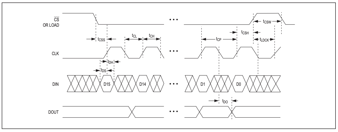
The MAX7219 gives us this timing diagram to follow when we want to send it data.
So to send data, we need to first take the CS line low. This activates the MAX7219, and it knows to listen for incoming data. Next, we set DIN and take CLK high. This will load the single bit of data on DIN into the MAX7219. Now we take CLK low in preparation for the next bit to be sent. We repeat this 8 times in total to send a byte of data.
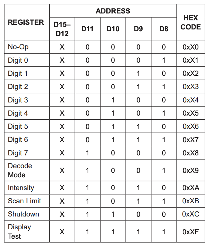
The MAX7219 expects two bytes of data to be sent each message. The first byte is an address, the second byte is the data value.
Sending SPI data using the Z80
So how do we do this on the Z80? Well, first we’re going to define some constants to help.
The SC129 is using IO Port 1.
OUTPUT_PORT EQU $01
As we said earlier, the Data bit is D0, the Clock is D1, and the Select line is D2. We call the Data bit MOSI, which stands for Master Out Slave In.
As you can see, we’re using binary to define the location. When we want to set the bit in one of these positions, we can use an OR statement, and when we want to clear the bit, we can AND the Compliment (the inverse).
So to enable the MAX7219 we want the SELECT line to be low, the CLK line to be low, and we will take MOSI high. We can use the following Z80 subroutine to do this.
select_max7219:
    ld a, 0 & ~SELECT & ~CLK | MOSI
    out (OUTPUT_PORT),a
    ret
To disable the MAX7219, we want the SELECT line to be high, the CLK line to be low, and we will take MOSI high.
deselect_max7219:
    ld a, 0 | SELECT & ~CLK | MOSI
    out (OUTPUT_PORT),a
    ret
To send a byte, need to send 8 bits of data. We pass the byte we want to send in the D register. To send a bit of data, we know we need to take SELECT and CLK low. We can prepare this and save it to the E register to reuse each bit. We are going to be shifting data into the MOSI bit, so before we save it to e, we shift it to the right. Now, for each bit we want to send, first load the A register with the value of the cached E register. We then pick up the next bit from the d register by shifting d to the left. This pushes the bit we want to send into the carry flag. We retrieve it by shifting the A register to the left so it sets the value of the carry flag into the MOSI bit. We send this, before ORing the CLK bit to take it high, and sending that.
That was quite a wordy explanation, but here’s the code so hopefully it makes more sense.
transmit_max7219_byte:
    push bc
    ld b, 8
    ld a, 0 &~SELECT &~CLK | MOSI
    rra
    ld e, a
.transmit_max7219_bit:
    ld a, e
    rl d
    rla
    out (OUTPUT_PORT), a
    or a, CLK
    out (OUTPUT_PORT), a
    djnz .transmit_max7219_bit
    pop bc
    ret
To send a two-byte instruction to the MAX7219, we need to combine the subroutines we’ve built. We need to select the MAX7219, send two bytes, then deselect it. We’ll pass the two bytes in registers b and c.
max7219_write:
    call select_max7219
    call transmit_max7219
    call deselect_max7219
    ret

transmit_max7219:
    ld d, b
    call transmit_max7219_byte
    ld d, c
    call transmit_max7219_byte
    ret
Controlling the MAX7219 using SPI
To tell the MAX7219 to turn on or off a LED, we send a column address in one byte, and the column data in the next. So, 8 columns of bits. However, we also need to send some additional command codes so the MAX7219 knows how to behave.
The MAX7219 can interface with 7-segment displays, but we don’t want any of this functionality, so we need to tell it not to decode any incoming display commands. We also want to make sure it is running on a low duty cycle to reduce power usage.
These are the commands I use to initialise the display.
    ld bc, 0x0C00       ; shutdown mode, this ensures the LEDs are off.
    call max7219_write
    ld bc, 0x0900       ; no decoding
    call max7219_write
    ld bc, 0x0A01       ; 3/32 intensity
    call max7219_write
    ld bc, 0x0B07       ; scan all 7 columns
    call max7219_write
    ld bc, 0x0F00       ; No display test
    call max7219_write
Once setup we can send the image. We send the column number in register b, and the column data in register c. So to send a cross I can use the following.
cross:
    dc %00000000
    dc %01000010
    dc %00100100
    dc %00011000
    dc %00011000
    dc %00100100
    dc %01000010
    dc %00000000
Finally, I turn the display on.
    ld bc, 0x0C01       ; normal operation - turn on the display
    call max7219_write
Building, deploying, and running on the RC2014
To assemble the code, I’m using the SjASMPlus Z80 assembler on my MacBook Pro. The RC2014 is running SCM, so to transfer the assembled code, I need to convert it into Intel hex before sending it across. I use z88dk-appmake to do this. Once across, I run the application using the “g” command in SCM.
So, to assemble my matrix.s source code to address $9000 and send it to my RC2014 using the serial device at /dev/tty.usbmodem03591, I would use the following. First, I would make sure I am connected to the RC2014 over serial using the following…
% minicom -c on --device /dev/tty.usbmodem03591
Next, I would open another Terminal shell and run the following…
Going back to minicom, I execute the code using the following…
g 9000
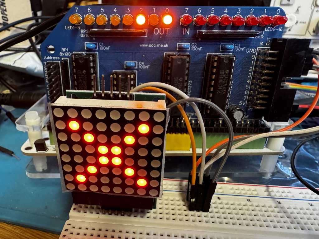
This will run the transmitted code, and my image will appear on the LED matrix.
Update
It’s been pointed out to me that the newer versions of SjASMPlus support the building of Intel HEX files directly, so we can skip the z88dk-appmake step. To build the hex files in SjASMPlus, we can use the following…
After taking part in the very enjoyable RetroChallenge in 2024 and 2025, I’ve decided to take part again in 2026.
This year, my plan is to use the SPI prototcol so my RC2014 computer can talk to various other SPI supporting devices.
SPI stands for Serial Peripherial Interface. It uses synchronous serial communication allowing a “master” to talk to “slave”. This gives us two lines MOSI – Master Out Slave In, and MISO – Master In Slave Out. There is a also a Clock line where 1 bit of data is sent and received each pulse of the clock, and a Select line that is used to activate a device. This allows multiple devices to share the same Clock, MOSI, and MISO lines, while using individual Select lines.
The Z80 microprocessor the RC2014 uses does not natively support SPI, so I will need to put together some basic hardware as well as writing software to support it.
Cookie Consent
We use cookies to improve your experience on our site. By using our site, you consent to cookies.
Websites store cookies to enhance functionality and personalise your experience. You can manage your preferences, but blocking some cookies may impact site performance and services.
Essential cookies enable basic functions and are necessary for the proper function of the website.
Name
Description
Duration
Cookie Preferences
This cookie is used to store the user's cookie consent preferences.
30 days
Statistics cookies collect information anonymously. This information helps us understand how visitors use our website.
Google Analytics is a powerful tool that tracks and analyzes website traffic for informed marketing decisions.
Contains information related to marketing campaigns of the user. These are shared with Google AdWords / Google Ads when the Google Ads and Google Analytics accounts are linked together.
90 days
__utma
ID used to identify users and sessions
2 years after last activity
__utmt
Used to monitor number of Google Analytics server requests
10 minutes
__utmb
Used to distinguish new sessions and visits. This cookie is set when the GA.js javascript library is loaded and there is no existing __utmb cookie. The cookie is updated every time data is sent to the Google Analytics server.
30 minutes after last activity
__utmc
Used only with old Urchin versions of Google Analytics and not with GA.js. Was used to distinguish between new sessions and visits at the end of a session.
End of session (browser)
__utmz
Contains information about the traffic source or campaign that directed user to the website. The cookie is set when the GA.js javascript is loaded and updated when data is sent to the Google Anaytics server
6 months after last activity
__utmv
Contains custom information set by the web developer via the _setCustomVar method in Google Analytics. This cookie is updated every time new data is sent to the Google Analytics server.
2 years after last activity
__utmx
Used to determine whether a user is included in an A / B or Multivariate test.
18 months
_ga
ID used to identify users
2 years
_gali
Used by Google Analytics to determine which links on a page are being clicked
30 seconds
_ga_
ID used to identify users
2 years
_gid
ID used to identify users for 24 hours after last activity
24 hours
_gat
Used to monitor number of Google Analytics server requests when using Google Tag Manager
1 minute
Marketing cookies are used to follow visitors to websites. The intention is to show ads that are relevant and engaging to the individual user.
A video-sharing platform for users to upload, view, and share videos across various genres and topics.
Registers a unique ID on mobile devices to enable tracking based on geographical GPS location.
1 day
VISITOR_INFO1_LIVE
Tries to estimate the users' bandwidth on pages with integrated YouTube videos. Also used for marketing
179 days
PREF
This cookie stores your preferences and other information, in particular preferred language, how many search results you wish to be shown on your page, and whether or not you wish to have Google’s SafeSearch filter turned on.
10 years from set/ update
YSC
Registers a unique ID to keep statistics of what videos from YouTube the user has seen.
Session
DEVICE_INFO
Used to detect if the visitor has accepted the marketing category in the cookie banner. This cookie is necessary for GDPR-compliance of the website.
179 days
LOGIN_INFO
This cookie is used to play YouTube videos embedded on the website.
2 years
VISITOR_PRIVACY_METADATA
Youtube visitor privacy metadata cookie
180 days
You can find more information in our Cookie Policy and .