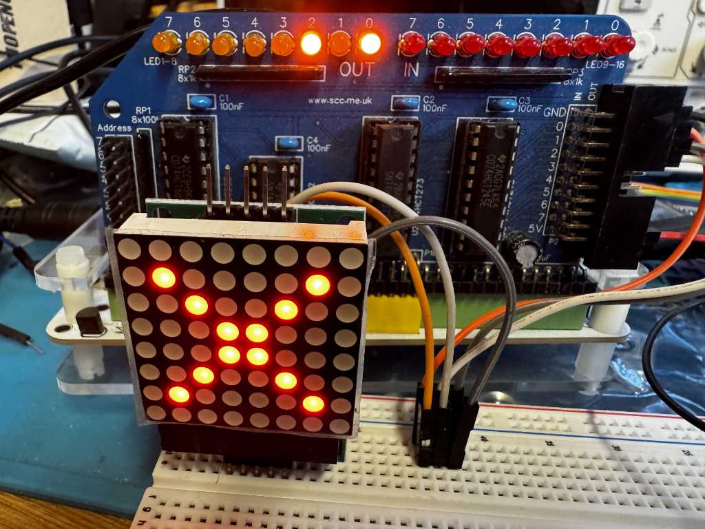
For the 2026 RetroChallenge I am exploring using SPI devices from a Z80 based RC2014 computer.
The first device I want to use is an 8×8 LED matrix (Amazon affilate link). Shelia Dixon has previously developed an 8×8 LED matrix display module for the RC2014, however this is directly interfaced to the RC2014 using two IO ports. I will be using a single port and communicating with it by bit banging the SPI protocol.
MAX7219 LED Matrix
The 8×8 LED matrix I’m using is a MAX7219 to handle the SPI communication and control the LEDs. It uses 5 wires from the RC2014
- VCC – +5V
- GND
- CS – Chip Select – This is active low
- CLK – Clock – Data is loaded when the clock goes from low to high
- DIN – Data In – 1 bit of data
I’m using the SC129 Digital IO module from Small Computing Central on the RC2014 for the digital output. This provides pins suitable for dupont connectors. You could use the official RC2014 Digital IO module, but you would have to modify it to add connections. In this case, it’s simplier to use the SC129 module. The SC129 is connected to the LED matrix module as follows…
| SC129 | MAX7219 LED Matrix module |
| +5V | VCC |
| GND | GND |
| OUT D0 | DIN |
| OUT D1 | CLK |
| OUT D2 | CS |
The MAX7219 gives us this iming diagram to follow when we want to send it data.
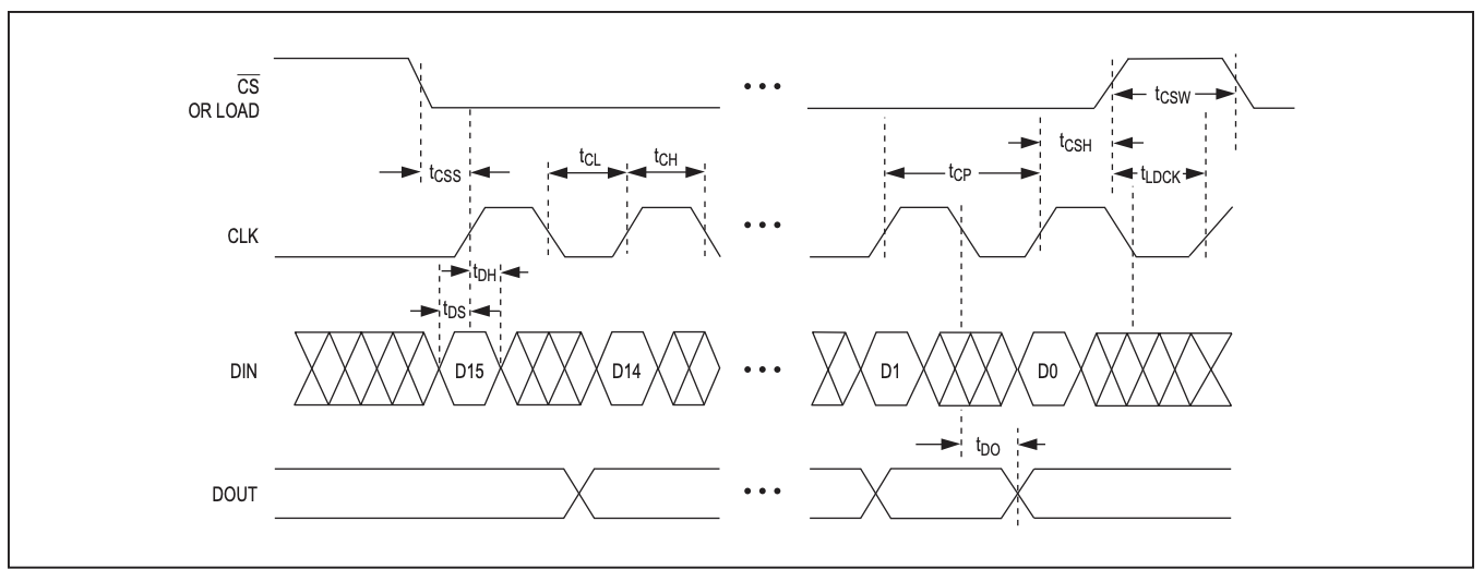
So to send data, we need to first take the CS line low. This tells activates the MAX7219 and it knows to listen for incoming data. Next we set DIN and take CLK high. This will load the single bit of data on DIN into the MAX7219. Now we take CLK low in preparation for the next bit to be sent. We repeat this 8 times in total to send a byte of data.
The MAX7219 expects two bytes of data to be sent each message. The first byte is an address, the second byte is the data value.

Sending SPI data using the Z80
So how do we do this on the Z80? Well first we’re going to define some constants to help.
The SC129 is using IO Port 1.
OUTPUT_PORT EQU $01As we said earlier, the Data bit is D0, the Clock is D1, and the Select line is D2. We call the Data bit MOSI, which stands for Master Out Slave In.
MOSI            EQU %00000001
CLK             EQU %00000010
SELECT          EQU %00000100
As you can see, we’re using binary to define the location. When we want to set the bit in one of these positions we can use an OR statement, and when we want to clear the bit we can AND the Compliment (the inverse).
So to enable the MAX7219 we want the SELECT line to be low, the CLK line to be low, and we will take MOSI high. We can use the following Z80 subroutine to do this.
select_max7219:
    ld a, 0 & ~SELECT & ~CLK | MOSI
    out (OUTPUT_PORT),a
    ret
To disable the MAX7219 we want the SELECT line to be high, the CLK line to be low, and we will take MOSI high.
deselect_max7219:
    ld a, 0 | SELECT & ~CLK | MOSI
    out (OUTPUT_PORT),a
    ret
To send a byte, need to send 8 bits of data. We pass the byte we want to send in the d register. To send a bit of data we know we need to take SELECT and CLK low. We can prepare this and save it to the e register to reuse each bit. We are going to be shifting data into the MOSI bit, so before we save it to e, we shift it to the right. Now for each bit we want to send, first load the a register with the value of the cached e restier. We then pick up the next bit from the d register by shifting d to the left. This pushes the bit we want to send into the carry flag. We retrieve it by shifting the a register to the left so it sets the value of the carry flag into the MOSI bit. We send this, before ORing the CLK bit to take it high, and sending that.
That was quite a wordy explaination, but here’s the code so hopefully it makes more sense.
transmit_max7219_byte:
    push bc
    ld b, 8
    ld a, 0 &~SELECT &~CLK | MOSI
    rra
    ld e, a
.transmit_max7219_bit:
    ld a, e
    rl d
    rla
    out (OUTPUT_PORT), a
    or a, CLK
    out (OUTPUT_PORT), a
    djnz .transmit_max7219_bit
    pop bc
    ret
To send a two byte instruction to the MAX7219 is expecting we need combine the subroutines we’ve built. We need to select the MAX7219, send two bytes, then deselect it. We’ll pass the two bytes in registers b and c.
max7219_write:
    call select_max7219
    call transmit_max7219
    call deselect_max7219
    ret

transmit_max7219:
    ld d, b
    call transmit_max7219_byte
    ld d, c
    call transmit_max7219_byte
    ret
Controlling the MAX7219 using SPI
To tell the MAX7219 to turn on or off a LED we send a column address in one byte, and the column data in the next. So 8 columns of bits. However, we also need to send some additional command codes so the MAX7219 knows how to behave.
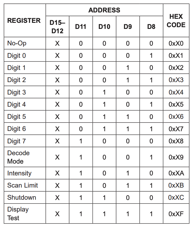
A full list of commands can be found in the MAX7219 datasheet.
The MAX7219 can interface with 7 segment displays, but we don’t want any of this functionality, so we need to tell it not to decode any incoming display commands. We also want to make sure it is running on a low duty cycle to reduce power usage.
These are the commands I use to initalise the display.
    ld bc, 0x0C00       ; shutdown mode, this ensures the LEDs are off.
    call max7219_write
    ld bc, 0x0900       ; no decoding
    call max7219_write
    ld bc, 0x0A01       ; 3/32 intensity
    call max7219_write
    ld bc, 0x0B07       ; scan all 7 columns
    call max7219_write
    ld bc, 0x0F00       ; No display test
    call max7219_write
Once setup we can send the image. We send the column number in register b, and the column data in register c. So to send a cross I can use the following.
    ld hl, cross
    ld b, 8
.send_image:
    ld c, (hl)
    inc hl
    call max7219_write
    djnz .send_image
cross:
dc %00000000
dc %01000010
dc %00100100
dc %00011000
dc %00011000
dc %00100100
dc %01000010
dc %00000000Finally I turn the display on.
    ld bc, 0x0C01       ; normal operation - turn on the display
    call max7219_write
Building, deploying, and running on the RC2014
To assemble the code I’m using the SjASMPlus Z80 assembler on my Macbook Pro. The RC2014 is running SCM, so to transfer the assembled code, I need to convert it into Intel hex before sending it across. I use z88dk-appmake to do this. Once across, I run the application using the “g” command in SCM.
So to assemble my matrix.s source code to address $9000 and send it to my RC2014 using the serial device at /dev/tty.usbmodem03591, I would use the following. First, I would make sure I am connected to the RC2014 over serial using the following…
% minicom -c on --device /dev/tty.usbmodem03591Next I would open another Terminal shell, and run the following…
% sjasmplus matrix.s --raw=matrix.z80
% z88dk-appmake +hex --org 0x9000 -b matrix.z80
% cat matrix.ihx > /dev/tty.usbmodem03591
Going back to minicom, I execute the code using the following…
g 9000This will run the transmitted code, and my image will appear on the LED matrix.