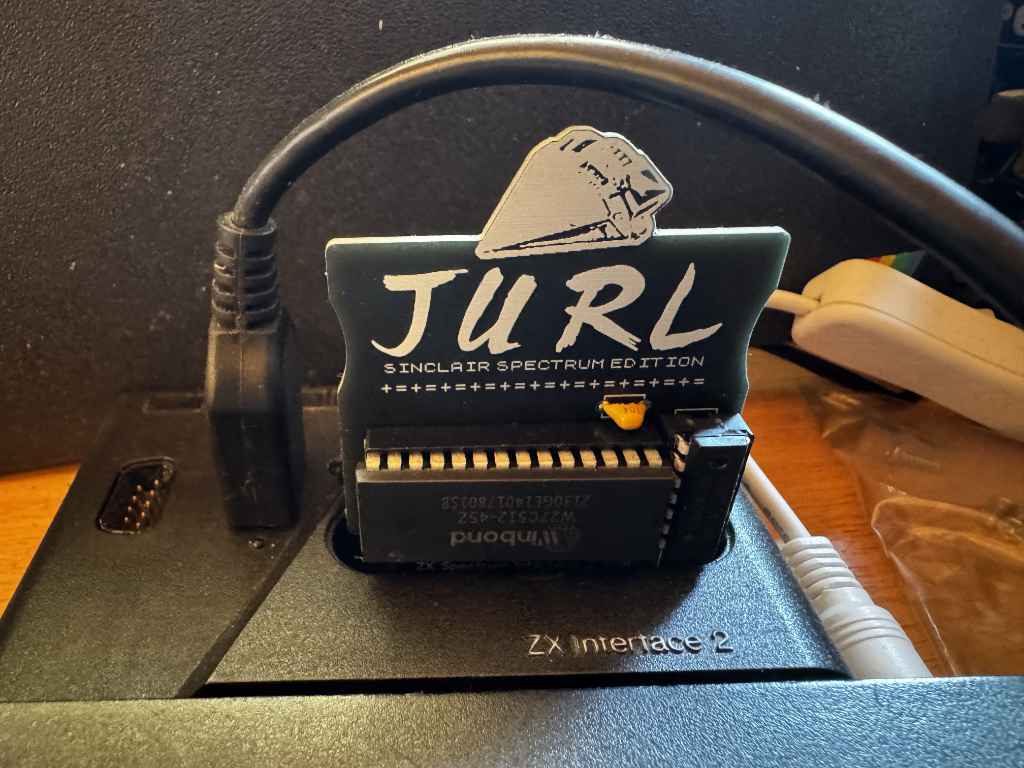
I’ve recently become interested in how ROM cartridges work on the ZX Spectrum. They were initially introduced by Sinclair Research with the release of the ZX Interface 2. This was a joystick interface that supported two Atari style 9 pin joysticks, and included a slot for a ROM cartridge. When a ROM cartridge was inserted and the Spectrum powered up, the internal ROM in the Spectrum would be disabled and replaced with the ROM in the cartridge. This meant games or other code on the cartridge would run instantly without needing to be loaded from cassette. However, it also meant games could not rely on any routines in Spectrum ROM, and must be standalone. The ROM cartridge is 16 kilobytes in size.
Looking at Jurl, the binary is 27,353 bytes in size. This is larger than the 16k size limit of the ROM cartridge. However, we can use compression to squeeze Jurl so it fits into a 16k cartridge. If we use ZX0 compression, we can shrink Jurl down to just 11,598 bytes.
Let’s start to put our ROM code together.
The code on the ROM will always start to execute from address 0. We can’t be sure the contents of the RAM will be blank. We could zero all the contents of the RAM, but it would be quicker to just make sure the BORDER, PAPER, and INK are all set to black so the user doesn’t see anything they shouldn’t.
The border is set using a Z80 out instruction to port 254. The paper and ink can be setting the attribute area of the screen memory to 0. This starts at address $5800 and is 767 bytes long. We can use a Z80 ldir instruction to quickly clear this.
; first, set the border to black
    ld a,0
    out (254),a           ; border black

; now set the background paper and ink to black by filling the attribute
; memory with 0s.
    ld hl,$5800           ; attribute memory start
    ld de,$5801
    ld bc,767
    ld (hl),a
    ldir                  ; fill all 768 attributes
Now we have a black screen, we can decompress the game and start it. We set the location of the compressed game in the HL register pair, and the destination address in DE before we call the ZX0 decompression routine. Once the game has decompressed we can just call it. We add a jump back to the call instruction incase the game returns. This ensures the game will just restart.
 ; decompress the game code into memory at gamelocation.
    ld hl,jurldata
    ld de,gamelocation
    call dzx0_standard

; run the game code.
.game_loop:
    call gamelocation

    jp .game_loop
Remember I said that the Spectrum’s ROM was replaced by the contents of the cartridge? Well, this causes a couple of problems as Jurl is expecting two things to be available in specific locations in the ROM. For the game to work, we will need to fix this.
Firstly, Jurl expects the Z80 to be running in IM1. This is interrupt mode 1 which means the Z80 will be interrupted periodically and will execute code at address $38. This would normally handle things like reading the keyboard, but Jurl doesn’t actually do anything with the data the interrupt is handling. This means we just need to handle the interrupt and return. So at address $38 we add the following.
im1:
    ei     ; re-enable interrupts
    reti   ; return
Secondly, Jurl also expects the ZX Spectrum’s font be available at address $3D00. I used the memory dump option in the Fuse emulator to save the font from the Spectrum’s ROM. I can then just include this binary data into my ROM at the correct address.
Once the source code has been assembled, the ROM cartridge binary can be tested in Fuse using the Media -> Cartridge menu option.
Building a physical ROM cartridge
Now I have a working binary, I can create a physical ROM cartridge to use in my ZX Interface 2.
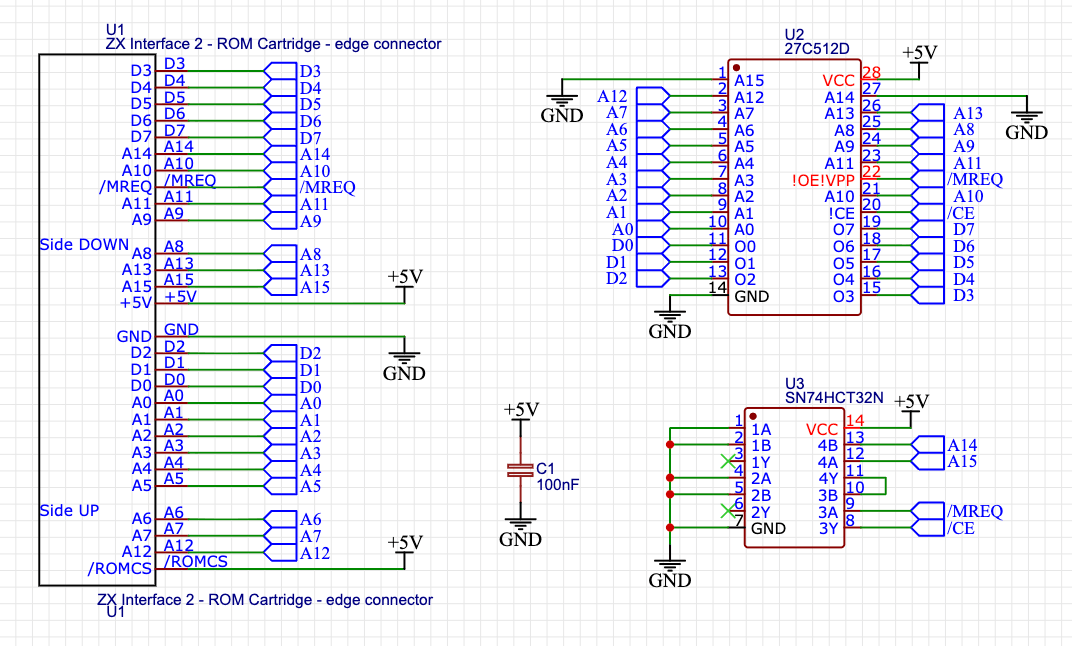
The ROM cartridge slot exposes address and data lines, as well as MREQ. I have several W27C512 EEPROMs I can use in the cartridge. This is a 64k cartridge but as I only need 16k, I can tie lines A14 and A15 to ground. I can also use a 74HCT32 OR gate to enable the EEPROM when A14, A15, and MREQ are all low.
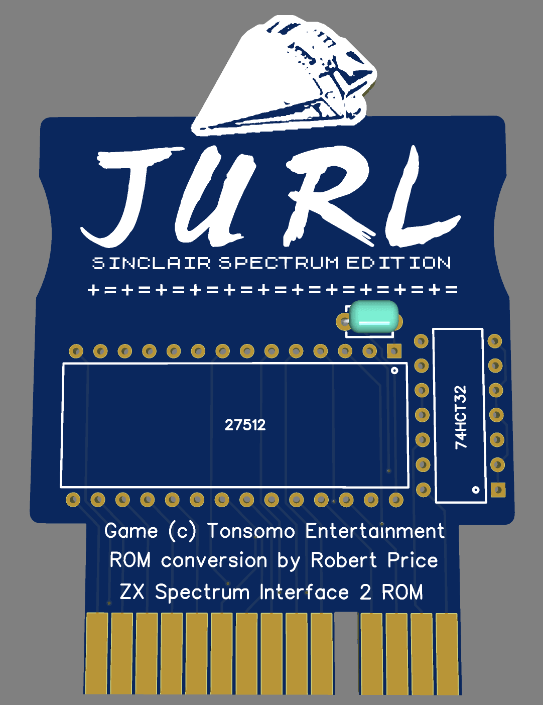
Now I have a circuit, I can use this to create a PCB. I have used EasyEDA to layout the PCB and also include a graphic of the spaceship from the loading screen.
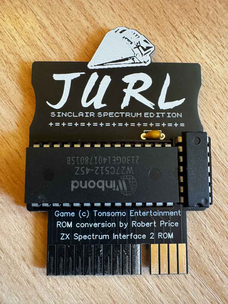
I sent the PCB design off to be manufactured, and when the boards arrived in the post I soldered one up and tested it out.
The card works well, and I now can play Jurl on my 48k ZX Spectrum instantly.
Acknowledgements
Before sharing this project, I wrote to Johnny to get his approval as the game is under copyright. I am very grateful that he kindly gave permission for me to share this.
In 1981, Sinclair Research introduced the ZX Printer. This was a small printer that connected to their ZX81 computer. It used special paper with an aluminium coating that could be burnt off by a passing print head. Sinclair’s later ZX Spectrum computer was also compatible with the ZX Printer.
A compatible printer called the Alphacom 32 / Timex Sinclair 2040 was also released. This used standard thermal paper. It used an external power supply instead of relying on that of the ZX81 or ZX Spectrum.
Both the ZX81 and ZX Spectrum are Z80-based, and so is the RC2014 computer. So I wondered if the RC2014 could use a ZX Printer? The belt inside my ZX Printer has perished and no longer works. I do have a working Alphacom 32 printer. Researching how I could interface the two devices, I found that Spencer Owen had already attempted this. He was able to get some output on the printer, but nothing usable.
The ZX Printer uses the following lines from the Z80 microprocessor.
A2 – LOW when addressing the printer.
IORQ – LOW when addressing the printer.
RD – LOW when reading
WR – LOW when writing
D0 – HIGH when reading if the printer is ready for the next data bit
D1 – Write HIGH to slow the motor. Write LOW for a faster motor speed.
D2 – Write HIGH to stop the motor, write LOW to start the motor.
D6 – LOW when reading if the printer is present.
D7 – HIGH when reading if it’s the start of a new line. Write HIGH to print a bit.
A7 – HIGH on the Alphacom 32 / Timex Sinclair 2040 when addressing the printer. The ZX Printer ignores this.
The printer also uses GND and +5V. The ZX Printer also uses +9V on the ZX81 and ZX Spectrum edge connector. The Alphacom 32 / Timex Sinclair 2040 doesn’t use +9V.
As decoding on just A2 would mean the printer showing on many addresses, I decided to use a 74HCT688 to decode A0 to A7 instead. This means I can avoid IO address clashes with other RC2014 modules. I decided to make this configurable via DIP switches to make it easy to move IO addresses. I send the output from the 74HCT688 to A2 on the printer. I wired A7 to +5V as I no longer need to decode this. I pass the other lines from the RC2014 to a ZX Spectrum compatible edge connector.
As the RC2014 doesn’t have a +9V power supply, I added a barrel socket for an external supply. I wired this to be center negative so I could use a ZX Spectrum power supply. As I don’t have a working ZX Printer, I’ve not been able to test this part of the circuit yet. The markings on the PCB are from the footprint, and these are the wrong way round.
Example Z80 Assembly Language
I set the DIP switches on my board to port $1. I also have an RC2014 Digital IO module on port $0. In my assembly language program, I use this to show the current line being printed, but this is optional.
The ZX Printer’s resolution is 256 pixels wide, so for this example, I converted the RC2014 logo to 256 pixels wide. This gave me a height of 42 lines for the image. The image I converted from didn’t scale very well, so it’s a bit of messy print.
I based my code on the printer routines in the ZX Spectrum ROM. The COPY command on a Spectrum prints out the current contents of the screen. I used this as my starting point, and modified the code to see a bitmap instead.
As timing is important, I have disabled interrupts while the code runs.
	OUTPUT zxprinter.z80

; Assemble using SjASMPlus.
;
; This program will print a bitmap image to a ZX printer.
; This code is based off code in the ZX Spectrum ROM.
; https://skoolkid.github.io/rom/asm/0ECD.html
;
; Robert Price - www.robertprice.co.uk

;        DEFINE+ UseDIO         ; Uncomment this line to use the Digital
                                ; IO board to show the current line being
                                ; printed.

PORT    EQU $1                  ; The output port to use for the printer.

        IFDEF UseDIO
DIOPORT EQU $0                  ; the output port for a RC2014 digial IO
                                ; board. This is used to show the current
                                ; line being printed.
        ENDIF

WIDTH   EQU 256                 ; the width of the image in pixels.
HEIGHT  EQU 42                  ; how many lines in the image to print.


        ORG $9000               ; The start of the program. This is where
                                ; the program will be loaded into memory.

        di                      ; disable interrupts

        ld b, HEIGHT            ; the number of lines to print is in B.
        ld hl, Buffer           ; The address of the bitmap stored in HL

Copy_Buffer:
        push bc
        call Copy_Line          ; print the current line
        pop bc

        IFDEF UseDIO
        ld a, b                 ; show the current line being printed on
                                ; the Digital IO LEDs.
        out (DIOPORT), a
        ENDIF

        djnz Copy_Buffer        ; loop back to print the next line.

        IFDEF UseDIO
        ld a, 0                 ; turn off the Digital IO LEDs
        out (DIOPORT), a
        ENDIF

Copy_End:
        ld a, $04               ; Bit 2 high stops the printer
        out (PORT), a           ; stop the printer

        ei                      ; enable interrupts

        ret                     ; end the program


Copy_Line:
        ld a, b                 ; Copy the pixel-line number.
        cp $03                  ; The A register will hold 0 until the
                                ; last two lines are being handled.
        sbc a, a
        and $02
        out (PORT), a           ; slow the motor for the last two lines.
        ld d, a                 ; the D register will hold either 0 or 2.

Copy_L_1;
                                ; on a ZX Spectrum this would test for
                                ; breaks and stop the printer.
                                ; let's add our own delay here to allow
                                ; the printer to catch up.
        push bc
        ld b, $ff
.delay:
        nop
        djnz .delay
        pop bc

Copy_L_2:
        in a, (PORT)            ; fetch the status of the printer.
        add a, a                ; double the value of A. This moves bit 6
                                ; which is the printer present flag to bit
                                ; 7 and the sign flag.
        ret m                   ; make an immediate return if the printer
                                ; is not present. (sign negative flag)

        jr nc, Copy_L_1         ; wait for the stylus to be ready.
        ld c, $20               ; there are 32 bytes.

Copy_L_3:
        ld e, (hl)              ; fetch a byte from the buffer.
        inc hl                  ; update the pointer
        ld b, $08               ; eight bits per byte

Copy_L_4:
        rl d                    ; move D left
        rl e                    ; move each bit into the carry
        rr d                    ; move D back again, picking up the carry
                                ; from E. The carry bit was the bit to print.

Copy_L_5:
        in a, (PORT)            ; fetch the status of the printer
        rra                     ; move bit 0 into the carry flag.
                                ; If bit 0 is high,
                                ; the printer is ready to receive data.
        jr nc, Copy_L_5         ; loop until the printer is ready

        ld a, d                 ; load the byte to send to the printer.
                                ; Bit 2 low starts the motor,
                                ; bit 1 high slows the motor,
                                ; bit 7 high prints
        out (PORT), a           ; send to the printer
        djnz Copy_L_4           ; print each bit.
        dec c                   ; decreate the line byte counter
        jr nz, Copy_L_3         ; loop until all 32 bytes are printed.
        ret

; The image we want to print
; In this case, it's the RC2014 logo at 256 pixels wide and 42 pixles high.
Buffer:
        dc $00, $00, $00, $00, $82, $00, $00, $00, $00, $00, $00, $00, $00, $00, $00, $00
        dc $00, $00, $00, $00, $82, $00, $00, $00, $00, $00, $00, $00, $00, $00, $00, $00
        dc $00, $00, $00, $00, $82, $00, $00, $00, $00, $00, $00, $00, $00, $00, $00, $00
        dc $00, $04, $10, $43, $08, $20, $00, $02, $08, $20, $82, $00, $00, $01, $04, $10
        dc $40, $00, $04, $10, $c2, $08, $00, $00, $02, $08, $00, $00, $06, $18, $01, $04
        dc $00, $04, $10, $c2, $08, $30, $00, $02, $08, $20, $06, $00, $00, $41, $04, $10
        dc $00, $00, $00, $00, $00, $00, $00, $00, $00, $00, $00, $00, $00, $00, $00, $10
        dc $60, $00, $04, $30, $82, $0c, $00, $00, $02, $0c, $00, $00, $04, $18, $01, $06
        dc $00, $04, $30, $82, $08, $30, $00, $02, $08, $01, $06, $00, $00, $41, $04, $10
        dc $c0, $00, $08, $20, $82, $0c, $00, $00, $06, $1c, $00, $00, $04, $18, $00, $06
        dc $00, $0c, $30, $c6, $18, $70, $00, $06, $18, $61, $86, $00, $00, $c3, $0c, $30
        dc $c0, $00, $0c, $31, $86, $1c, $00, $00, $06, $18, $00, $00, $0c, $38, $03, $0c
        dc $00, $ff, $ff, $ff, $ff, $f0, $00, $7f, $ff, $ff, $fe, $00, $0f, $ff, $ff, $ff
        dc $c0, $00, $ff, $ff, $ff, $fc, $00, $00, $7f, $f8, $00, $00, $7f, $f8, $3f, $fc
        dc $00, $08, $37, $df, $70, $40, $00, $06, $fb, $ef, $0c, $20, $00, $df, $7d, $e0
        dc $84, $00, $0d, $f7, $84, $10, $00, $00, $04, $18, $00, $00, $08, $30, $02, $0c
        dc $00, $08, $20, $00, $00, $41, $01, $04, $00, $00, $08, $30, $20, $c0, $00, $01
        dc $86, $02, $18, $00, $04, $10, $40, $01, $04, $10, $00, $00, $08, $30, $02, $08
        dc $00, $18, $70, $00, $00, $41, $81, $06, $00, $00, $08, $30, $20, $c0, $00, $01
        dc $07, $06, $18, $00, $04, $10, $60, $01, $08, $30, $00, $00, $08, $30, $00, $18
        dc $00, $10, $60, $00, $00, $43, $01, $06, $00, $00, $08, $30, $20, $c0, $00, $01
        dc $06, $04, $18, $00, $04, $00, $c0, $02, $08, $30, $00, $00, $08, $30, $04, $18
        dc $00, $38, $e0, $00, $00, $c3, $03, $1c, $00, $00, $1c, $70, $71, $c0, $00, $23
        dc $8e, $06, $38, $00, $0c, $71, $c0, $07, $1c, $70, $00, $00, $1c, $70, $0e, $38
        dc $01, $ff, $e0, $00, $0f, $ff, $3f, $fc, $00, $00, $ff, $e3, $ff, $80, $00, $1f
        dc $fe, $7f, $f8, $00, $7f, $ff, $c0, $3f, $ff, $f0, $00, $01, $ff, $e0, $7f, $f8
        dc $00, $10, $40, $00, $00, $82, $02, $0c, $00, $00, $00, $00, $00, $00, $00, $c3
        dc $00, $0c, $30, $02, $08, $20, $80, $02, $00, $60, $00, $00, $18, $00, $04, $10
        dc $00, $00, $c0, $00, $00, $82, $02, $08, $00, $00, $00, $00, $00, $00, $00, $c3
        dc $00, $0c, $30, $03, $00, $00, $80, $00, $10, $60, $00, $04, $18, $00, $08, $30
        dc $00, $20, $c0, $00, $00, $06, $00, $18, $00, $00, $00, $00, $00, $00, $00, $83
        dc $00, $08, $30, $03, $00, $41, $80, $00, $10, $60, $00, $04, $18, $00, $08, $30
        dc $00, $20, $c0, $00, $01, $06, $04, $18, $00, $00, $00, $00, $00, $00, $00, $83
        dc $00, $08, $30, $03, $00, $41, $80, $00, $10, $60, $00, $04, $18, $00, $08, $30
        dc $03, $ff, $c0, $00, $0f, $fe, $3f, $f8, $00, $00, $00, $00, $00, $00, $0f, $ff
        dc $00, $ff, $f0, $7e, $07, $ff, $80, $01, $ff, $e0, $00, $7f, $f0, $00, $ff, $f0
        dc $00, $61, $80, $00, $03, $fe, $0e, $38, $00, $00, $00, $00, $00, $00, $01, $ff
        dc $00, $18, $70, $0e, $00, $c3, $80, $00, $30, $c0, $00, $1c, $70, $00, $18, $70
        dc $00, $41, $04, $10, $41, $00, $04, $30, $00, $00, $00, $00, $02, $08, $21, $80
        dc $00, $10, $60, $04, $00, $03, $00, $00, $20, $c0, $00, $08, $20, $00, $10, $60
        dc $00, $41, $04, $10, $43, $00, $00, $30, $00, $00, $00, $00, $06, $18, $41, $80
        dc $00, $10, $60, $06, $00, $83, $00, $00, $20, $c0, $00, $08, $30, $00, $10, $60
        dc $00, $41, $04, $10, $83, $00, $08, $30, $00, $00, $00, $00, $06, $10, $41, $80
        dc $00, $10, $60, $0e, $00, $83, $00, $00, $20, $c0, $00, $00, $60, $00, $10, $60
        dc $00, $41, $0c, $30, $83, $00, $08, $30, $00, $00, $00, $00, $04, $10, $41, $80
        dc $00, $10, $60, $0c, $00, $83, $00, $00, $21, $c0, $00, $18, $60, $00, $10, $e0
        dc $0f, $ff, $ff, $ff, $ff, $00, $ff, $f0, $00, $00, $00, $00, $7f, $ff, $ff, $80
        dc $03, $ff, $c0, $fc, $1f, $ff, $00, $07, $ff, $80, $01, $ff, $e0, $03, $ff, $e0
        dc $00, $c3, $ff, $ff, $86, $00, $18, $70, $00, $00, $00, $00, $0e, $fb, $ff, $00
        dc $00, $20, $c0, $0c, $01, $86, $00, $00, $61, $80, $00, $10, $c0, $00, $30, $80
        dc $00, $83, $00, $00, $04, $10, $10, $60, $00, $00, $00, $01, $04, $00, $00, $00
        dc $00, $20, $80, $08, $01, $06, $00, $00, $41, $00, $00, $10, $42, $08, $20, $82
        dc $00, $83, $00, $00, $04, $18, $10, $60, $00, $00, $00, $03, $0e, $00, $00, $00
        dc $00, $20, $c0, $18, $01, $06, $00, $00, $41, $80, $00, $30, $82, $08, $20, $83
        dc $00, $83, $00, $00, $04, $18, $10, $60, $00, $00, $00, $02, $0c, $00, $00, $00
        dc $00, $00, $c0, $18, $01, $06, $00, $00, $c3, $80, $00, $20, $82, $08, $20, $03
        dc $01, $86, $00, $00, $0c, $38, $10, $e0, $00, $00, $00, $02, $0c, $00, $00, $00
        dc $00, $41, $80, $18, $03, $0e, $00, $00, $c3, $00, $00, $20, $82, $18, $61, $86
        dc $1f, $fe, $00, $00, $ff, $fb, $ff, $e0, $00, $00, $00, $3f, $fc, $00, $00, $00
        dc $07, $ff, $81, $f8, $3f, $fc, $00, $0f, $ff, $00, $03, $ff, $ff, $ff, $ff, $fe
        dc $01, $06, $00, $00, $08, $30, $30, $c0, $00, $00, $00, $06, $1c, $00, $00, $00
        dc $00, $41, $00, $f0, $02, $0c, $00, $00, $87, $00, $01, $f7, $df, $70, $41, $be
        dc $01, $04, $00, $00, $08, $30, $20, $c0, $00, $00, $06, $00, $18, $00, $00, $10
        dc $c0, $40, $0c, $00, $02, $0c, $00, $00, $82, $00, $00, $00, $00, $00, $41, $00
        dc $01, $0e, $00, $00, $08, $30, $20, $c0, $00, $01, $06, $04, $18, $00, $00, $30
        dc $c0, $02, $0c, $00, $02, $0c, $00, $01, $87, $00, $00, $00, $00, $00, $41, $80
        dc $03, $0c, $00, $00, $08, $30, $20, $c0, $00, $01, $06, $04, $18, $00, $00, $20
        dc $c0, $82, $0c, $00, $06, $1c, $00, $01, $06, $00, $00, $00, $00, $00, $03, $00
        dc $03, $0c, $00, $00, $18, $60, $61, $c0, $00, $03, $0e, $0c, $38, $00, $00, $30
        dc $c0, $c3, $0c, $00, $06, $18, $00, $01, $8e, $00, $00, $00, $00, $00, $c3, $00
        dc $3f, $fc, $00, $01, $ff, $e3, $ff, $80, $00, $1f, $fc, $7f, $f8, $00, $03, $ff
        dc $cf, $ff, $f8, $00, $7f, $f8, $00, $1f, $fe, $00, $00, $00, $00, $0f, $ff, $00
        dc $02, $18, $00, $00, $10, $60, $41, $00, $00, $03, $00, $08, $20, $80, $00, $61
        dc $80, $06, $18, $40, $06, $00, $00, $03, $08, $00, $00, $00, $00, $00, $82, $00
        dc $02, $18, $00, $00, $10, $40, $01, $00, $00, $83, $00, $08, $20, $82, $18, $61
        dc $80, $04, $10, $41, $06, $00, $10, $c2, $08, $20, $c0, $00, $00, $00, $02, $00
        dc $04, $18, $00, $00, $00, $60, $00, $08, $20, $83, $00, $08, $20, $86, $10, $41
        dc $80, $04, $10, $41, $06, $00, $30, $82, $08, $20, $c0, $00, $00, $01, $06, $00
        dc $04, $18, $00, $00, $00, $c0, $02, $08, $20, $83, $00, $08, $01, $04, $10, $41
        dc $80, $04, $10, $c2, $0e, $00, $20, $82, $08, $20, $c0, $00, $00, $01, $06, $00
        dc $ff, $f8, $00, $03, $ff, $c0, $3f, $ff, $ff, $ff, $01, $ff, $ff, $ff, $ff, $ff
        dc $80, $ff, $ff, $ff, $fc, $03, $ff, $ff, $ff, $ff, $80, $00, $00, $1f, $fe, $00
        dc $7f, $f8, $00, $01, $ff, $c0, $3f, $ff, $ff, $fe, $00, $ff, $ff, $ff, $ff, $ff
        dc $80, $7f, $ff, $ff, $fc, $01, $ff, $ff, $ff, $ff, $80, $00, $00, $1f, $fe, $00
        dc $3e, $f8, $00, $01, $f7, $c0, $1f, $7d, $ff, $be, $00, $7b, $ef, $fe, $fb, $ef
        dc $80, $3e, $fb, $df, $7c, $01, $f7, $df, $79, $ef, $80, $00, $00, $0f, $bc, $00
Essentially, DTMF uses two tones played at the same time to encode a digit.
To send the digit ‘1’, I need to play a 697Hz tone and 1209Hz.
The SID chip can play multiple tones at the same time, so this should be possible. However, the DTMF tones use sine waves, which the SID chip can’t generate. It can generate triangle waves which I think would be the closest equivalent.
The timing on the original SID was dependent on the frequency of the TV signal. In PAL regions this is 50Hz, and in NTSC regions this is 60Hz. I’m not sure which the SID-Ulator is using, so I had to generate values for the frequencies for both.
For PAL regions this is
f * 17.0284087
For NTSC regions this is
f * 16.4043888
So in the PAL region, the integer value of ‘f’ for 697 would be
697 * 17.0284087 = 11869
I calculated these values for both PAL and NTSC in Excel, along with the hex values. The hex values are easier to split into high and low bytes that are needed by the SID chip.
PAL
PAL (Hex)
NTSC
NTSC (Hex)
697
11868.80085
2E5C
11433.85897
2CA9
1209
20587.34609
506B
19832.90602
4D78
I then needed to actually play these notes, so I wrote a BASIC program to do this. I went with the NTSC values initially for the high and low bytes of the frequency.
Instead of using memory mapping like the Commodore 64, the SID-Ulator module uses Z80 IO ports. So rather than POKEing an address to configure the SID, we use the Z80 OUT command. The SID-Ulator is configured to use IO ports 212 for the register, and 213 for the data.
10 S=0 :REG=212 :DAT=213
20 REM CONFIGURE CHANNEL 1 (697 Hz)
30 OUT REG,S+1: OUT DAT, 0    : REM CLEAR FREQUENCY LOW BYTE
40 OUT REG,S: OUT DAT, 0      : REM CLEAR FREQUENCY HIGH BYTE
50 OUT REG,S+5: OUT DAT, 9    : REM SET ATTACK=0.6ms, DECAY=0.6s (9 = 00001001)
60 OUT REG,S+6: OUT DAT, 240  : REM SET SUSTAIN=MAX, RELEASE=6s (240 = 11110000)
70 OUT REG,S+4: OUT DAT, 17   : REM SET TRIANGLE WAVE (BIT 4) AND GATE (BIT 0)
80 OUT REG,S: OUT DAT, &ha9     : REM SET FREQUENCY LOW BYTE FOR 697
90 OUT REG,S+1: OUT DAT, &h2c   : REM SET FREQUENCY HIGH BYTE FOR 697
100 REM CONFIGURE CHANNEL 2 (1209 Hz)
110 OUT REG,S+8: OUT DAT, 0   : REM CLEAR FREQUENCY LOW BYTE
120 OUT REG,S+7: OUT DAT, 0   : REM CLEAR FREQUENCY HIGH BYTE
130 OUT REG,S+12: OUT DAT, 9  : REM SET ATTACK=0.6ms, DECAY=0.6s (9 = 00001001)
140 OUT REG,S+13: OUT DAT, 240: REM SET SUSTAIN=MAX, RELEASE=6s (240 = 11110000)
150 OUT REG,S+11: OUT DAT, 17 : REM SET TRIANGLE WAVE (BIT 4) AND GATE (BIT 0)
160 OUT REG,S+7: OUT DAT, &h78 : REM SET FREQUENCY LOW BYTE FOR 1209 Hz
170 OUT REG,S+8: OUT DAT, &h4d  : REM SET FREQUENCY HIGH BYTE FOR 1209 Hz
180 REM PLAY BOTH TONES FOR 1 SECOND
190 FOR T = 1 TO 1000 : REM LOOP FOR 1 SECOND (APPROXIMATELY)
200 NEXT T
210 REM RELEASE BOTH NOTES
220 OUT REG,S+4: OUT DAT, 16  : REM RELEASE CHANNEL 1 NOTE (CLEAR GATE BIT)
230 OUT REG,S+11: OUT DAT, 16 : REM RELEASE CHANNEL 2 NOTE (CLEAR GATE BIT)
240 END
Running this, I got something that certainly sounded like DTMF tones.
I tried plugging the output of the SID-Ulator into my DTMF decoder to confirm this was correct. Unfortunately, the DTMF decoder could not detect a valid tone.
I thought this must be because I needed to use the PAL values. Again, it certainly sounded like DTMF tones when run, but the DTMF decoder could not detect a valid tone.
Unfortunately, I’ve not been able to generate DTMF tones using the SID-Ulator.
What went wrong
I’m not sure what has gone wrong exactly, but I have a few ideas.
The calculations for the frequencies could be incorrect. I used the formula I found on the SID reference website. This may not be quite right. I don’t have a scope to check the frequencies that are being output.
The triangle wave isn’t a suitable replacement for the sine wave. There isn’t much I can do about this as the SID doesn’t support sine waves.
The output from the SID-Ulator isn’t suitable for my DTMF decoder. I don’t think this is the case as I can hear the tones when connected to my speaker.
I may also have just used incorrect values for the settings causing the output to distort.
If anyone has any suggestions, I’d love to hear them.
Now I want to go the opposite way, and have my RC2014 generate DTMF tones.
I own one of Ed Brindley’s excellent YM2149 Sound Cards for the RC2014, so I want to use this to generate the DTMF tones. Mine has Colin Piggot’s Quazar ZXTT card attached to match the clock speeds used in the ZX Spectrum. This gives a clock speed of 1.7734MHz, which will be important when generating the DTMF tones.
DTMF works by sending two tones for each key. One high frequency, one low frequency. These are mapped to the numbers 0 to 9, characters * and #, and the letters A to D.
1209 Hz
1336 Hz
1477 Hz
1633 Hz
697 Hz
1
1
3
A
770 Hz
4
5
6
B
852 Hz
7
8
9
C
941 Hz
*
0
#
D
The AY-3-8910 has 3 channels of sound available, so we only need two of these to generate a DTMF tone.
We need to calculate a divider for the based on the clock speed for each tone. This is the clockspeed divided by (16 x the frequency).
So for a 697Hz tone being generated with a clock speed of 1.7734Mhz, the calculation would be 1.7734 / ( 16 * 697) = 159.
We can do the same for the other tones, which gives us the following values.
697 Hz
159
770 Hz
144
852 Hz
130
941 Hz
118
1209 Hz
92
1336 Hz
83
1477 Hz
75
1633 Hz
68
We are going to use channels A and B on the AY-3-8910 to generate our DTMF tone. So to play the DTMF tone for “1”, we need to play a 697 Hz tone on channel A, and a 1209H Hz tone on channel B. Looking at the table above, this means channel A needs the value 159, and channel B the value 92.
A simple Z80 assembly language program to play these tones would look something like this.
AY_REGISTER_PORT EQU 0xD8
AY_DATA_PORT    EQU 0xD0

CHANNEL_A       EQU 0x00
CHANNEL_B       EQU 0x02

		ld a, CHANNEL_A
		out (AY_REGISTER_PORT), a
		ld a, 159
		out (AY_DATA_PORT), a

		ld a, CHANNEL_B
		out (AY_REGISTER_PORT), a
		ld a, 92
		out (AY_DATA_PORT), a
We can expand this and write a Z80 assembly language program to play the tones for each key once using the following code. In this example I keep the tone pairs in memory and then look up the values before playing them for a short duration then stopping the sound output before moving to the next pair.
		OUTPUT DTMFAYEncoder.z80

		ORG $9000

AY_REGISTER_PORT EQU 0xD8
AY_DATA_PORT    EQU 0xD0

CHANNEL_A       EQU 0x00
CHANNEL_B       EQU 0x02
ENABLE          EQU 0x07
AMPLITUDE_A     EQU 0x08
AMPLITUDE_B     EQU 0x09

VOLUME          EQU 0x0F

; the tones we need for the AY chip
DIVIDER_697     EQU 159
DIVIDER_770     EQU 144
DIVIDER_852     EQU 130
DIVIDER_941     EQU 118
DIVIDER_1209    EQU 92
DIVIDER_1336    EQU 83
DIVIDER_1477    EQU 75
DIVIDER_1633    EQU 68

init:
; set volume on channel A
		ld a, AMPLITUDE_A
		out (AY_REGISTER_PORT), a
		ld a, VOLUME
		out (AY_DATA_PORT), a

; set volume on channel B
		ld a, AMPLITUDE_B
		out (AY_REGISTER_PORT), a
		ld a, VOLUME
		out (AY_DATA_PORT), a


; iterate over all the codes we have and play them out
		ld b, tonecodelen
		ld hl, tonecodes
.loop:
		ld d, (hl)
		call playTone
		call enableAB
		call delay
		call stopTone
		call shortdelay

		inc hl
		djnz .loop

; stop the tones
		call stopTone

		ret


; -----------------------------
; SUBROUTINES
; -----------------------------

; a short delay
delay:
		push bc
		ld bc, $8888
		call dodelay
		pop bc
		ret

; an even shorter delay
shortdelay:
		push bc
		ld bc, $1500
		call dodelay
		pop bc
		ret

; dodelay does the actual delaying
; pass the delay length in BC
dodelay:
		push de
		push af
.loop:
		dec bc
		ld a, b
		or c
		jr nz, .loop
		pop af
		pop de
		ret

; enable channels A and B on the AY chip
enableAB:
		push af
		ld a, ENABLE
		out (AY_REGISTER_PORT), a
		ld a, 0xFC
		out (AY_DATA_PORT), a
		pop af
		ret

; stop tones playing on the AY chip
stopTone:
		push af
		ld a, ENABLE
		out (AY_REGISTER_PORT), a
		ld a, 0x3F 		        ; disable all channels
		out (AY_DATA_PORT), a
		pop af
		ret

; play a tone
; pass the ASCII character for the tone in D
playTone:
		push af
		push bc
		push de

		call getTone

		ld a, CHANNEL_A
		out (AY_REGISTER_PORT), a
		ld a, b
		out (AY_DATA_PORT), a

		ld a, CHANNEL_B
		out (AY_REGISTER_PORT), a
		ld a, c
		out (AY_DATA_PORT), a

		pop de
		pop bc
		pop af
		ret

; get the tones two tones for character in D
; return the two tones in registers BC
getTone:
		push af
		push hl

		ld e, 0

		ld hl, tonecodes
.loop:
		ld a, (hl)
		cp d
		jr z, .gottone
		inc hl
		inc e
		inc e
		jr .loop
.gottone:
		ld a, e
		ld hl, tones

; we now need to add A to HL
		add a, l
		ld l, a
		adc a, h
		sub l
		ld h, a
; get the first tone in B
		ld b, (hl)
		inc hl
; get the second tone in C
		ld c, (hl)

		pop hl
		pop af
		ret

; the tone codes in order. We use this to get
; the both tone codes from tones
tonecodes:	dc '1234567890*#ABCD'
tonecodelen     EQU $ - tonecodes

tones:
tone1:		dc DIVIDER_697, DIVIDER_1209            ; 1
tone2:		dc DIVIDER_697, DIVIDER_1336            ; 2
tone3:		dc DIVIDER_697, DIVIDER_1477            ; 3
tone4:		dc DIVIDER_770, DIVIDER_1209            ; 4
tone5:		dc DIVIDER_770, DIVIDER_1336            ; 5
tone6:		dc DIVIDER_770, DIVIDER_1477            ; 6
tone7:		dc DIVIDER_852, DIVIDER_1209            ; 7
tone8:		dc DIVIDER_852, DIVIDER_1336            ; 8
tone9:		dc DIVIDER_852, DIVIDER_1477            ; 9
tone0:		dc DIVIDER_941, DIVIDER_1336            ; 0
tonestar:	dc DIVIDER_941, DIVIDER_1209            ; *
tonehash:	dc DIVIDER_941, DIVIDER_1477            ; #
toneA:		dc DIVIDER_697, DIVIDER_1633            ; A
toneB:		dc DIVIDER_770, DIVIDER_1633            ; B
toneC:		dc DIVIDER_852, DIVIDER_1633            ; C
toneD:		dc DIVIDER_941, DIVIDER_1633            ; D
It’s easy to test our code as we build the DTMF decoder module. We can simply plug the output from the sound card into the DTMF decoder. We can see the decoded tones showing on the debugging LEDs.
To perform IO on the Z80 I needed to use a SFR (Special Function Register). When a variable created using an SFR is read or written to, this is converted directly into Z80 in and out instructions.
My DTMF Decoder module is running on an RC2014 Classic 2 on IO port 1. To declare an SFR in my C code to access this port, I can use the following…
Now when I read from variable io_dtmf, this is mapped to an in instruction on the Z80. So to read this port, I can do the following…
uint8_t in = io_dtmf;
Now the unsigned 8 bit integer variable “in” holds the value of whatever was on IO port 1 when the variable was assigned.
To write the decoder program, I can use the same approach as my earlier Z80 assembly language program. This reading the IO port, and seeing if the STQ bit is set. If it is, we can then read the input and map this to the known DTMF codes. This is then printed to the console. We also need to make sure we’ve not already handled the current tone, so we need to store and check against this.
This is my working C code to decode incoming DTMF tones using my DTMF Decoder module for the RC2014.
// zcc +rc2014 -subtype=basic -clib=sdcc_iy -v -m -SO3 --max-allocs-per-node200000 dtmf.c -o dtmf -create-app
// this will compile to $8000, so can be run in SCM using "g 8000"
#pragma output CRT_ORG_CODE = 0x8000
#pragma output REGISTER_SP = 0xFC00
#define __IO_DTMF_PORT  0x01
__sfr __at __IO_DTMF_PORT io_dtmf;
#include <stdio.h>
char *codes = "D1234567890*#ABC";
uint8_t previous = 0xff;
void main(void) {
printf("DTMF Decoder\n");
while (1) {
uint8_t in = io_dtmf;
// is the STQ bit set?
if (in & 0b00010000) {
// we only want the lower 4 bits so mask out any others.
uint8_t current = in & 0b00001111;
if (current != previous) {
printf("%c", codes[current]);
previous = current;
}
} else {
previous = 0xff;
}
}
}
Dual-tone multi-frequency, commonly known as DTMF, is a technology used in telecoms systems that uses audible tones to represent keys on a touch-tone phone.
You have probably heard this will navigating a menu on your phone, such as “Press 1 for …, Press 2 for….”, etc.
While browsing on AliExpressing for some parts for another project, it suggested I may like the MT8870 module (affiliate link). This is a small 5V DTMF decoder module with digital outputs. I thought this would be ideal for an RC2014 project.
We’re interested in 7 pins on this module. +5v and GND are for powering the module. STQ, D0, D1, D2, and D3 are for the decoded tones. The STQ line goes high when a decoded tone is present. The actual code is a 4 bit value stored on D0, D1, D2, and D3.
We can pass this output to a 74HCT245 transceiver which we can enable using a 74HCT688 to decode an input address on the RC2014, along with a 74HCT32 to check the RD and IORQ lines.
I’m using an RC2014 Classic 2 for this project, so inout port 1 is free, but I know this isn’t necessarily the case on more advanced RC2014s. Because of this I’ve put an 8 inline switch module on the 74HCT688 so I change the address if necessary.
I am also adding some LEDs on the input lines so I can see the incoming data visually. The MT8870 has some SMD LEDs on board to do this, but the built-in pin headers I want to use will mean these face the RC2014 module PCB and so won’t be visible. I’ve gone for green for the STQ line, blue for the data lines.
The PCB looks like this.
Decoding the input using Z80 assembly language
I want to write a small Z80 assembly language program to print out any incoming DTMF tones to the terminal.
I’m using the SCM monitor program on my RC2014 Classic 2 computer to load and execute my assembly language program. This gives a handy print character to the terminal routine I can use. I pass the ASCII character I want to print in register A, the value $02 in register C, and execute RST $30. I can wrap this into my own subroutine called printchar. This gives me the flexibility to swap to another output method such as an LCD screen in future.
; pass the character to print in register A
; This uses SCM to print back to the terminal.
printchar:
		push bc
		ld c, $02 	; SCM API function $02 - print character
		rst $30
		pop bc
		ret
I will need to debounce any input I read from the decoder module. This is because the value will be present for longer than the first read I make. To do this I will need to check if STQ is high and compare this to the last value read. If it’s the same, I know I have already handled this value. However, when STQ goes low, I need to reset the last value read to a dummy value else it won’t detect multiple presses of the same button.
Once I have the data, I can map it to the correct character. I do this by having the valid decoded characters in order, and then simply the incoming character value as an offset to this list.
My final code looks like this.
		OUTPUT DTMFDecoder.z80

		ORG $9000

; Input data from the DTMF encoder is
; Bits 0-3 = number data (D0, D1, D2, D3)
; Bit 4    = new data flag (STQ)
; Bits 5-7 = unused.

; The input port where we can find the DTMF decoder
DTMFDecoder     EQU 1

; masks for handling the input data.
NEW_INPUT_MASK  EQU %00010000
DATA_INPUT_MASK EQU %00001111

; Flags to show if the data is new or not.
DataRead        EQU $FF
DataClear       EQU $00

; Register C holds the data read flag. This is set to DataRead when we've
; read a byte, and set to DataClear when we are safe to read a byte.
		ld c, DataClear

mainloop:
; read the data from the input port DTMFDecoder and store this in register B.
		in a, (DTMFDecoder)
		ld b, a
; see if the new data flag bit has been set. If it has go to datapresent.
		and NEW_INPUT_MASK
		jr nz, datapresent

; clear Register C as we have no data to read, and loop again.
		ld c, DataClear
		jr mainloop

datapresent:
; we have data present so check if register C is set to DataRead. If it
; is we know we have already handled that input so can loop again.
		ld a, DataRead
		cp c
		jr z, mainloop

; set register C to DataRead to flag we have handled this input.
		ld c, DataRead

; get the input into register A and mask out the button press bit.
		ld a, b
		and DATA_INPUT_MASK

; decode the character from the input and find it in the charmap.
		ld hl, charmap

; add the value of a to hl
		add a, l
		ld l, a
		adc a, h
		sub l
		ld h, a

; get the character from the charmap and print it.
		ld a, (hl)
		call printchar

; now loop again.
		jr mainloop


; pass the character to print in register A
; This uses SCM to print back to the terminal.
printchar:
		push bc
		ld c, $02 	; SCM API function $02 - print character
		rst $30
		pop bc
		ret

; The DTMF characters in order.
charmap:
		db 'D1234567890*#ABC'
I wanted to try writing some C code for my RC2014 Classic II computer, so I thought I’d document how I did this.
I’ve not written C for a few years, so I’m quite rusty. My example code may not be the most efficient, but I have compiled it, and then run it on my RC2014.
I use a Mac, so I installed z88dk. This is a C and Assembly language toolkit especially designed to target Z80 based computers like the RC2014.
One of the simplest programs is “Hello World”. This simply prints the string “Hello World” to the screen. In this case, the screen on the RC2014 is actually a serial terminal.
I’m planning on running this using SCM. This is a simple monitor program that the RC2014 Classic II ships with in ROM. I can use this to load in hex code and execute it from a serial terminal.
This is my example Hello World C program. I saved it as “hello.c”.
+rc2014 tells the compiler we are targeting the RC2014 when generating code.
-subtype=basic tells the compiler we are building code to run under BASIC or SCM. More advanced RC2014s can run CPM, and we could change the subtype if we wanted to target that.
-clib=sdcc_iy tells the compiler which C library we are using.
-v gives us a verbose output.
-m generates map files when compiling.
-SO3 tells the compiler to use level 3 optimisation. This should be the most efficient.
–max-allocs-per-node 200000 is another optimisation that is recommended in the documentation.
-create-app will create .ihx hex files that can be sent to SCM to load the program.
Once compiled, I use a cat command to send the generated hello.ihx file to SCM over an active serial connection.
cat hello.ihx > /dev/tty.usbXXXXX
Finally, in my terminal (I use minicom) I type the following into SCM to execute my program from address 0x8000.
g 8000
And I magically see the words “Hello World” in my terminal.
When we’re working on a multi language application, we need to be aware of the user’s language ensure they receive content in their own language.
Mendix has great language support, and it also has great caching on the client side. These can cause problems together when you change the language of a user in your application, it may not always be reflected back to local cache.
There is a way around this, we can use the Mendix Client API to force a retrieve of the data from the application. We need to use an XPath request to ensure we bypass the cache.
let xPath = "//System.Language[System.User_Language=\"" + mx.session.getUserId() + "\"]";
We have the current user’s session ID, so we can retrieve the System.Language using this a constraint on the System.User_Language association.
Now we can just use an mx.data.get call to retrieve it.
mx.data.get({
    xpath: xPath,
    filter: {
        amount: 1
    },
    callback: function(obj) {
        let lang = obj[0].jsonData.attributes.Code.value;
        console.log("Current language is " + lang);
    }
});
In this example, we are just echoing the language code back to the user on the console.
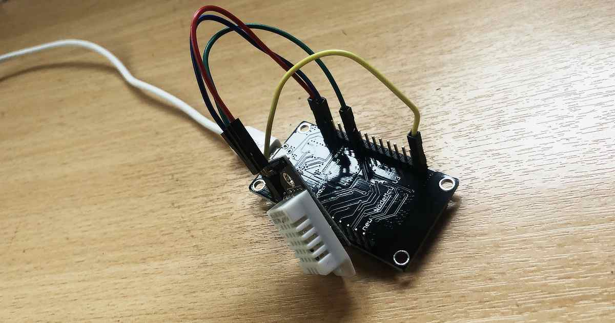
I recently built a simple temperature sensor using a NodeMCU (ESP8266) and a DHT22. This reads the temperature and humidity roughly every 30 seconds and pushes the data to a MQTT server so I can handle the data elsewhere.
The NodeMCU wakes up every 30 seconds and connects to my local WiFi network. Once connected it takes a sensor reading and publishes it to my MQTT server. It then delays for a few seconds to ensure the message is sent, then goes into deep sleep.
The deep sleep is a function I wasn’t aware of on the ESP8266 before. It just a case of wiring up D0 to RST and calling ESP.deepsleep() in the code. When the device wakes up, it’s like its been turned on for the first time.
As the purpose of the sensor was to just send the data to a MQTT server in a simple format, I needed to write something to listen to the published messages the device was sending.
I was able to do this using a simple NodeRED program to listen to incoming MQTT messages, and send them to debug console, and to a CSV file for later processing.
I added a timestamp and built the CSV line using a mustache template. This is then appended to a CSV file I put in my /tmp directory.
To test the data is being logged correctly, I wrote a simple R script parse the data and plot a diagram from it. As the CSV had no header columns, I had to rename the first column names as read_csv used the first line values by default.
The Nordic Thingy:52 is a compact multi-sensor prototyping platform. It exposes a variety of configurable sensors and actuators over Bluetooth.
Modern versions of the Google Chrome browser support the Web Bluetooth API. This means we can write JavaScript that runs in a web browser to talk to Bluetooth devices. We can use this to get Chrome to talk to a Nordic Thingy:52.
Timeseries have released the Bluetooth (BLE) Connector module to the Mendix App Store. This allows developers to connect and write to Bluetooth devices from a Mendix app. These are exposed as JavaScript actions.
If we want to change the colour of the Nordic Thingy:52’s LED, how do we do this from a Mendix app?
We can use the DeviceConnect JavaScript Action in a Nanoflow to connect to a Nordic Thingy:52. The Bluetooth (BLE) Connector module doesn’t allow data to be written to a device. We need this functionality to tell the Nordic Thingy:52 what colour we want to the LED to show. So we will need to write our own JavaScript Action to do this.
Create the SetLED JavaScript Action
JavaScript Actions in Mendix are very easy to write. We create a JavaScript Action called SetLED. This needs to take 3 String parameters. A “primaryServiceUUID”, a “characteristicUUID”, and “mycolour”. The “primaryServiceUUID” describes what type of service we want to talk to. The “characteristicUUID” is the specific characteristic, in this case the LED. Finally, “mycolour” is the colour we want to show described as a CSS style rgb string (e.g. “rgb(10, 255, 10)”).
A Mendix JavaScript Action works by using a JavaScript promise to return data to a Nanoflow. Mendix has created a small scaffolded bit of JavaScript for us to change.
The first thing we need to do is to see if Bluetooth is supported. We do this by trying to access the window.gattServer. If it’s not available, we need to reject the Promise.
var gattServer = window.gattServer;
  if(gattServer){
    // Bluetooth available
  } else {
    return Promise.reject("No gatt server found");
  }
Now we need to try to access the LED characteristic on the device. We do this by creating a new Promise within which we get the primary service, then the LED characteristic. At this point we should be able to talk to the device and issue an instruction for the LED.
return new Promise((resolve, reject) => {
    gattServer.getPrimaryService(primaryServiceUUID)
    .then( (s) => {
        return s.getCharacteristic( characteristicUUID );
    })
    .then( (c) => {
        characteristic = c;
        return c;
    })
    .then(characteristic => {
        // do something with the LED
        resolve(true);
    });
});
The data is sent as binary using the writeValue method of the characteristic. We need to convert our RGB string into binary values before we send this. We can extract the individual values for R, G, and B using a regular expression. We can then insert these into a JavaScript Uint8ClampedArray. The Uint8ClampedArray prevents values under 0 and over 255. This helps us avoid buffer overflows which could cause bugs.
const match = mycolour.match(/rgba?\((\d{1,3}), ?(\d{1,3}), ?(\d{1,3})\)?(?:, ?(\d(?:\.\d?))\))?/);
let buffer = new Uint8ClampedArray(4);
buffer.set([1, match[1], match[2], match[3]], 0);

characteristic.writeValue(buffer);
Our final action should look like this…
 // This file was generated by Mendix Studio Pro.
//
// WARNING: Only the following code will be retained when actions are regenerated:
// - the code between BEGIN USER CODE and END USER CODE
// Other code you write will be lost the next time you deploy the project.

/**
 * @param {string} primaryServiceUUID
 * @param {string} characteristicUUID
 * @param {string} mycolour
 * @returns {boolean}
 */
function SetLED(primaryServiceUUID, characteristicUUID, mycolour) {
 // BEGIN USER CODE
 var gattServer = window.gattServer;
 if(gattServer){
 return new Promise((resolve, reject) => {
            gattServer.getPrimaryService(primaryServiceUUID)
            .then( (s) => {
 return s.getCharacteristic( characteristicUUID );
            })
            .then( (c) => {
                characteristic = c;
 return c;
            })
            .then(characteristic => {
 const match = mycolour.match(/rgba?\((\d{1,3}), ?(\d{1,3}), ?(\d{1,3})\)?(?:, ?(\d(?:\.\d?))\))?/);
 let buffer = new Uint8ClampedArray(4);
                buffer.set([1, match[1], match[2], match[3]], 0);

                characteristic.writeValue(buffer);
                resolve(true);
            });
        });
    } else {
 return Promise.reject("No gatt server found");
    }
 // END USER CODE
}
Now we have our JavaScript action, we can wire it into a Mendix app.
Using the SetLED JavaScript Action
We need to add a non persistable entity to hold our RGB string. We’ll call this “LED”, and add one String attribute “RGBString”.
Add a Data view to the page, and set its data source to the a new Nanoflow called CreateLED. All the Nanoflow needs to do is create an instance of our LED entity.
Mendix have provided an excelled RGB colour picker in the App Store called Color Picker. We can drop this into our Data view setting the Color Attribute field to the RGB string in our new LED entity. Set the Color Format to RGB. In the Appearance Tab set the Picker type to Hue. Now when we use the colour picker, it will save the selected value to our LED entity. That’s great, but we want to actually change the colour on Nordic Thingy:52. To do this, we need to go to Events and On change call a new Nanoflow we’ll call ChangeLED.
ChangeLED needs to first connect to the Nordic Thingy:52. We do this using the DeviceConnect JavaScript action from the Bluetooth (BLE) Connector. This takes a Primary service UUID of ” ef680100-9b35-4933-9b10-52ffa9740042″. It also takes an Optional service UUID of ” ef680300-9b35-4933-9b10-52ffa9740042″. I found these values in the example JavaScript code on Nordic’s GitHub account. When this is called it will trigger a prompt to connect to a Bluetooth device.
Once we are connected, we call our SetLED JavaScript action. The Primary service UUID is ” ef680300-9b35-4933-9b10-52ffa9740042″. This was the value we used as the optional UUID when we connected. For the Characteristic UUID we use the value “ef680301-9b35-4933-9b10-52ffa9740042” for the LED. For Mycolour we use the value in the RGBString attribute in our LED entity.
We can now run the App.
Running the App
The first time the ChangeLED Nanoflow is run it will prompt to connect to a Bluetooth device. This is where we look for our Nordic Thingy:52. Future requests are not prompted for while in the same session.
If we’ve connected to our device the LED should now be changing colour to match the value in the colour picker.
Conclusion
Hopefully this should be enough information to get you connecting to a Bluetooth device and sending data.
If you aren’t using Mendix at the moment it’s free to get started, you just need to signup for a Mendix account.
Cookie Consent
We use cookies to improve your experience on our site. By using our site, you consent to cookies.
Websites store cookies to enhance functionality and personalise your experience. You can manage your preferences, but blocking some cookies may impact site performance and services.
Essential cookies enable basic functions and are necessary for the proper function of the website.
Name
Description
Duration
Cookie Preferences
This cookie is used to store the user's cookie consent preferences.
30 days
Statistics cookies collect information anonymously. This information helps us understand how visitors use our website.
Google Analytics is a powerful tool that tracks and analyzes website traffic for informed marketing decisions.
Contains information related to marketing campaigns of the user. These are shared with Google AdWords / Google Ads when the Google Ads and Google Analytics accounts are linked together.
90 days
__utma
ID used to identify users and sessions
2 years after last activity
__utmt
Used to monitor number of Google Analytics server requests
10 minutes
__utmb
Used to distinguish new sessions and visits. This cookie is set when the GA.js javascript library is loaded and there is no existing __utmb cookie. The cookie is updated every time data is sent to the Google Analytics server.
30 minutes after last activity
__utmc
Used only with old Urchin versions of Google Analytics and not with GA.js. Was used to distinguish between new sessions and visits at the end of a session.
End of session (browser)
__utmz
Contains information about the traffic source or campaign that directed user to the website. The cookie is set when the GA.js javascript is loaded and updated when data is sent to the Google Anaytics server
6 months after last activity
__utmv
Contains custom information set by the web developer via the _setCustomVar method in Google Analytics. This cookie is updated every time new data is sent to the Google Analytics server.
2 years after last activity
__utmx
Used to determine whether a user is included in an A / B or Multivariate test.
18 months
_ga
ID used to identify users
2 years
_gali
Used by Google Analytics to determine which links on a page are being clicked
30 seconds
_ga_
ID used to identify users
2 years
_gid
ID used to identify users for 24 hours after last activity
24 hours
_gat
Used to monitor number of Google Analytics server requests when using Google Tag Manager
1 minute
Marketing cookies are used to follow visitors to websites. The intention is to show ads that are relevant and engaging to the individual user.
A video-sharing platform for users to upload, view, and share videos across various genres and topics.
Registers a unique ID on mobile devices to enable tracking based on geographical GPS location.
1 day
VISITOR_INFO1_LIVE
Tries to estimate the users' bandwidth on pages with integrated YouTube videos. Also used for marketing
179 days
PREF
This cookie stores your preferences and other information, in particular preferred language, how many search results you wish to be shown on your page, and whether or not you wish to have Google’s SafeSearch filter turned on.
10 years from set/ update
YSC
Registers a unique ID to keep statistics of what videos from YouTube the user has seen.
Session
DEVICE_INFO
Used to detect if the visitor has accepted the marketing category in the cookie banner. This cookie is necessary for GDPR-compliance of the website.
179 days
LOGIN_INFO
This cookie is used to play YouTube videos embedded on the website.
2 years
VISITOR_PRIVACY_METADATA
Youtube visitor privacy metadata cookie
180 days
You can find more information in our Cookie Policy and .