The RetroChallenge may have finished, but I have a few more things to add.
Chartreuse on Mastodon pointed out that the SNES controller is quite like the NES controller. Instead of returning a single byte, it returns two bytes. The first byte is the same as the NES controller; the second contains extra buttons.
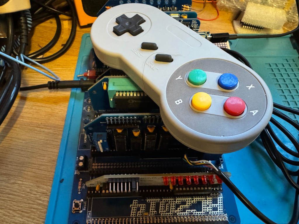
I wanted to see if my existing work could be easily extended to use a SNES controller, so I bought one on AliExpress. I also bought a SNES extension lead so I could cut it in half and add Dupont sockets to the wires. This means I could wire it directly to the RC2014 module I designed for the NES controller using one of the debug connectors I added to the PCB.
The SNES controller uses a different connector, but the pins work in the same way. This diagram shows the 5 pins we are interested in, and how we need to wire them up to the RC2014 NES controller module.
Writing a reusable Z80 routine
As there are two bytes being returned, I can’t just call my get_buttons routine. This will toggle the Latch twice, so I will never get the extra buttons.
Instead, I have to toggle Latch one at the start of the routine, and call a cut down version of the original get_buttons routine that reads the 8 bits twice. The first byte returned will be the original NES buttons. The second byte will be the extra buttons on the SNES controller. Instead of returning a single byte in register a, I will instead use register pair de. Register d will hold the NES button data, and register e will hold the SNES button data.
; SNESController.inc
; Definitions and subroutine to read SNES controller button states
; Robert Price - 1st November 2025


; The Z80 port address to use for the controller interface.
NES_PORT    EQU $01

; The bit masks for the controller interface lines.
CLOCK   EQU $01
LATCH   EQU $02
DATA    EQU $01


; subroutine to read the NES controller button states.
; returns the button states in DE registers.
; register D contains the high byte, and register E the low byte.
; All other registers are preserved.
; The high byte is like the NES controller, low has the extra SNES buttons.
get_buttons:
        push af           ; save af registers
        push bc           ; save bc registers

; pulse the LATCH line low to high and back to low again.
        xor a               ; set a to 0
        out (NES_PORT), a
        ld a, LATCH
        out (NES_PORT), a
        xor a               ; set a to 0
        out (NES_PORT), a

        call .get_buttons
        ld d, a             ; store the button states in register d
        call .get_buttons
        ld e, a             ; store the button states in register e

        pop bc              ; restore bc registers
        pop af              ; restore af registers

        ret                 ; return to caller with button states in a


.get_buttons:
; setup the loop counter to read 8 buttons.
        ld b, 8             ; 8 buttons to read.

; now we rebuild the byte into register c. As we are setting all 8 bits,
; we don't need to worry about clearing c first.
.loop:
; read the controller button states
        in a, (NES_PORT)    ; read the DATA line

; move the DATA bit into register c to rebuild the send byte
        srl a               ; shift right to get the DATA bit into carry
        rr c                ; rotate carry into bit 7 of c

; pulse the CLOCK line to read the next button.
        ld a, CLOCK
        out (NES_PORT), a
        xor a               ; set a to 0
        out (NES_PORT), a

; loop to read all buttons.
        djnz .loop

; return the button states in register a
        ld a, c             ; put the final button states in a
        ret
Using the new Z80 routine
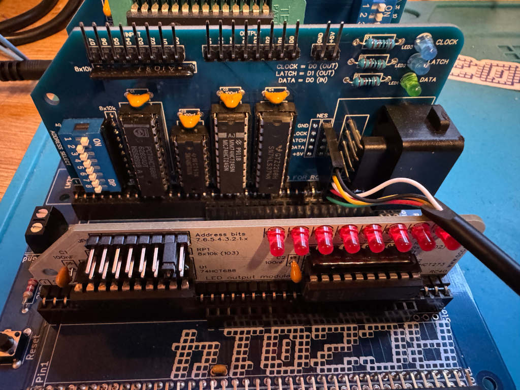
To test the new routine, I can use LEDs as before. I have two modules that can display an 8-bit value using LEDs. A RC2014 Digital IO module at IO address 0, and a SC134 module at IO address 2. I will display one returned byte on one of the modules, and the second returned byte on the other module. This can be run using SCM as before.
 ; A simple button reading program for the RC2014 Z80 computer running SCM
 ; this version outputs the SNES button states to a LED output
 ; Robert Price - 1st November 2025

        ORG $9000

; the Z80 port address to use for the LED output.
; This expects two Digital IO ports to be connected to the RC2014,
; one at IO address 0 for the high byte, and one at IO address 2 for the low byte.
LED_PORT_H  EQU $00
LED_PORT_L  EQU $02

main:
; get the button states from the SNES controller
        call get_buttons     ; call the get_buttons subroutine
        ld a, d              ; get the high byte button states
        cpl                  ; invert the bits in register a so pressed buttons are 1, and unpressed are 0
        out (LED_PORT_H), a  ; output the button states to the LED port

        ld a, e              ; get the low byte button states
        cpl                  ; invert the bits in register a so pressed buttons are 1, and unpressed are 0
        out (LED_PORT_L), a  ; output the button states to the LED port

        jr main              ; repeat forever

        INCLUDE "SNESController.inc"

        END
In previous posts, I’ve covered how to read an NES controller from an RC2014 computer, and also how to use an 8×8 LED matrix. I now want to combine these and use the NES controller to move a pixel on the LED matrix.
The first thing we want to do is to draw a pixel in the top left corner of the LED matrix. To do this, I’ll use register b for the Row data and register c for the Column data. We need to set a single bit in each because we only want a single pixel lit.
        ORG $9000

ROW     EQU 0
COLUMN  EQU 2

setup:
        ld b, 0b00000001  ; Row bit for the pixel
        ld c, 0b10000000  ; Column bit for the pixel

main:

.draw_pixel:
        xor a             ; clear a
        out (COLUMN), a   ; clear the columns
        ld a, b           ; get the current row bit
        out (ROW), a      ; select the row
        ld a, c           ; get the column data for this row
        out (COLUMN), a   ; output the column data

        jr main           ; repeat forever

        END
Now that we have a pixel, we need to read the NES controller and react to movement on the joypad.
We can use Z80 rlc and rrc operations to move the single bit to the left or right in the Row and Column registers. If we reach the end of the byte, the bit will roll over to the other end of the byte.
To test which button is being pressed, we can use a bit operation. If the button isn’t being pressed, we can jump ahead to test the next button.
In our main loop, we can add the following.
UP_BTN   EQU $04
DOWN_BTN EQU $05
LEFT_BTN EQU $06
RIGHT_BTN EQU $07

main:
        call get_buttons   ; Get NES controller button states in A

.test_left:
        bit LEFT_BTN, a
        jr nz, .test_right
        rlc c
.test_right:
        bit RIGHT_BTN, a
        jr nz, .test_up
        rrc c
.test_up:
        bit UP_BTN, a
        jr nz, .test_down
        rrc b
.test_down:
        bit DOWN_BTN, a
        jr nz, .draw_pixel
        rlc b

.draw_pixel:
At the moment, this is executing far too fast, so we end up with an entire row or column being lit. We need to add a delay. We can write a very simple Z80 routine to just loop X times as a simple delay.
delay:
ld de, 50000
.delay_loop:
dec de
ld a, d
or e
jr nz, .delay_loop
ret
The final working code
Putting this all together, we end up with the following code…
; A simple program to move a pixel on an 8x8 LED matrix
; connected to the RC2014 Z80 computer.
; Robert Price - 19th October 2025
ORG $9000
ROW EQU 0
COLUMN EQU 2
UP_BTN EQU $04
DOWN_BTN EQU $05
LEFT_BTN EQU $06
RIGHT_BTN EQU $07
setup:
ld b, 0b00000001 ; Row bit for the pixel
ld c, 0b10000000 ; Column bit for the pixel
main:
call get_buttons ; Get NES controller button states in A
.test_left:
bit LEFT_BTN, a
jr nz, .test_right
rlc c
.test_right:
bit RIGHT_BTN, a
jr nz, .test_up
rrc c
.test_up:
bit UP_BTN, a
jr nz, .test_down
rrc b
.test_down:
bit DOWN_BTN, a
jr nz, .draw_pixel
rlc b
.draw_pixel:
xor a ; clear a
out (COLUMN), a ; clear the columns
ld a, b ; get the current row bit
out (ROW), a ; select the row
ld a, c ; get the column data for this row
out (COLUMN), a ; output the column data
call delay ; small delay to make movement visible
jr main ; repeat forever
delay:
ld de, 50000
.delay_loop:
dec de
ld a, d
or e
jr nz, .delay_loop
ret
        INCLUDE "NESController.inc"

        END
As part of the 2025 RetroChallenge I’ve been developing an NES controller module for the RC2014 computer.
Up until now, I’ve just been outputting to a terminal. However, I’d like to use something a bit more visual on the RC2014. I’ve decided to use Peacock Media’s 8×8 LED matrix module for this.
The module works by outputting an 8-bit value to one IO port for the row and another 8-bit value to another IO port for the column. These describe which LEDs should be enabled. Each bit in the byte refers to either a row or a column.
The default IO port for the row is 0, and the default IO port for the column is 2.
If I want the top left corner to light, I need to set bit 8 of the column and bit 1 of the row.
If you have the SCM (Small Computer Monitor) program running on an RC2014, you can quickly test it out using the following.
o 0 1
o 2 80
This sets the row to hexadecimal 1, which in binary is 00000001, and the column to hexadecimal 80 which in binary is 1000000.
A smiley face in BASIC
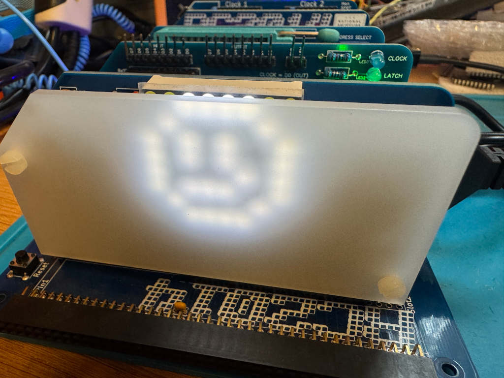
In the documentation for the 8×8 module, Shelia Dixon gives us an example BASIC program to draw a smiley face.
This works by rapidly updating the pixels rather than keeping them permanently on. Repeated fast enough, persistence of vision makes the LEDs appear to be on constantly.
10 FOR I=0 TO 7
20 READ R,C
30 OUT 2,0 : OUT 0,R : OUT 2,C
40 NEXT I
50 RESTORE
60 GOTO 10
1000 DATA 1,60, 2,66, 4,169, 8,169
1010 DATA 16,133, 32,185, 64,66, 128,60
A smiley face in Z80 assembly language
I wanted to convert the BASIC program to Z80 assembly language to help me better understand how this works.
I take a similar approach to the BASIC program. I iterate over a loop 8 times to represent the current Row. I keep this counter in register b. In register c, I keep the current bit the row is pointing to. In each iteration, I read a byte of data from memory that represents the Column. The position in memory is pointed to by register pair hl. Once the data has been output, I then shift the value in register c to the right so it points to the next row.
The final code looks like this.
; A simple program to display a smiley face on an 8x8 LED matrix
; connected to the RC2014 Z80 computer.
; Robert Price - 19th October 2025
;
; Based on the original BASIC example by Shiela Dixon
        ORG $9000

ROW     EQU 0
COLUMN  EQU 2

main:
        ld b, 8           ; 8 rows to display
        ld c, 0b10000000  ; start with bit 7 set for row 8
        ld hl, data       ; point to the smiley data
.loop:
        xor a             ; clear a
        out (COLUMN), a   ; clear the columns
        ld a, c           ; get the current row bit
        out (ROW), a      ; select the row
        ld a, (hl)        ; get the column data for this row
        out (COLUMN), a   ; output the column data
        inc hl            ; point to next row data
        srl c             ; shift to next row bit
        djnz .loop        ; loop for all 8 rows

        jr main           ; repeat forever

data:
        db 0b00111100     ; 60
        db 0b01000010     ; 66
        db 0b10111001     ; 185
        db 0b10000101     ; 133
        db 0b10101001     ; 169
        db 0b10101001     ; 169
        db 0b01000010     ; 66
        db 0b00111100     ; 60

        END
I wanted to write a reusable Z80 assembly language subroutine to read the NES controller and return the status of the buttons in a register.
The principle is the same as my previous posts in that I have to pulse the Latch and Clock lines, and read data 1 bit at a time from the Data line. However, this time I want to store all 8 returned bits in a single byte that I can return in a register.
I had some feedback from Jon Jones on Bluesky who suggested I could optimise my previous code by replacing the ld a,0 instruction with xor a. This is a byte smaller, and is quite a neat trick as a value exclusive or’d with itself will always be 0.
I have also been learning more about how shifting and rotating works on the Z80. When I read my bit from the data line, if I use a slr a instruction, it will push the bit that has just been read onto the carry flag. I can then use rr c to move the contents of register c one to the right and fill bit 7 with the contents of the carry flag. Doing this 8 times will fill the c register with all the values I need.
The finished subroutine looks like this.
; NESController.inc
; Definitions and subroutine to read NES controller button states
; Robert Price - 19th October 2025


; The Z80 port address to use for the controller interface.
NES_PORT    EQU $01

; The bit masks for the controller interface lines.
CLOCK   EQU $01
LATCH   EQU $02
DATA    EQU $01


; subroutine to read the NES controller button states.
; returns the button states in register a.
; all other registers are preserved.
get_buttons:
        push bc           ; save bc registers

; pulse the LATCH line low to high and back to low again.
        xor a               ; set a to 0
        out (NES_PORT), a
        ld a, LATCH
        out (NES_PORT), a
        xor a               ; set a to 0
        out (NES_PORT), a

; setup the loop counter to read 8 buttons.
        ld b, 8             ; 8 buttons to read. This will be decremented to 0.

; now we rebuild the byte into register c. As we are setting all 8 bits,
; we don't need to worry about clearing c first.
.loop:
; read the controller button states
        in a, (NES_PORT)    ; read the DATA line

; move the DATA bit into register c to rebuild the send byte
        srl a               ; shift right to get the DATA bit into carry
        rr c                ; rotate carry into bit 7 of c

; pulse the CLOCK line to read the next button.
        ld a, CLOCK
        out (NES_PORT), a
        xor a               ; set a to 0
        out (NES_PORT), a

; loop 8 times to read all buttons.
        djnz .loop

; return the button states in register a
        ld a, c             ; put the final button states in a

        pop bc              ; restore bc registers

        ret                 ; return to caller with button states in a
Testing the subroutine
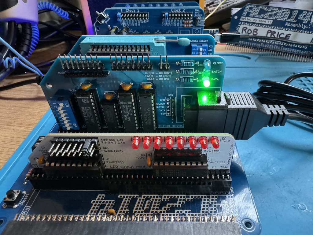
To test the new subroutine I made use of the SC134 LED output card I was kindly given at RC2014 Assembly. The standard RC2014 Digital IO card will also work. I have assigned this to IO address 2.
The code simply reads the NES controller, inverts the bits using the cpl instruction, outputs the value to the LEDs, and loops.
I need to use the cpl instruction as the NES controller returns a pressed button as 0. If I didn’t do this, the LEDs would be on apart from any button being pressed. cpl inverts all the bits in the a register so any button being pressed is now lit.
; the Z80 port address to use for the LED output.
LED_PORT    EQU $02

main:
; get the button states from the NES controller
        call get_buttons     ; call the get_buttons subroutine
        cpl                  ; invert the bits in register a so pressed buttons are 1, and unpressed are 0
        out (LED_PORT), a    ; output the button states to the LED port
        jr main              ; repeat forever
In my last post, I wrote about using MS-Basic on my RC2014 to bit-bang an NES controller. In this post, I want to use Z80 assembly language to do the same. I want to be able to press a button on the controller and have its name printed on the serial terminal.
The first thing we need to do is set up a few things.
The code will need to run at 0x9000, so an ORG statement will tell the assembler to build the code to run from there.
ORG $9000
The NES controller module will be located at the Z80 IO port 1.
PORT EQU $01
The Clock bit is 1, the Latch bit is 2, and the Data bit is 1.
CLOCK   EQU $01
LATCH   EQU $02
DATA    EQU $01
I’ll be using Stephen Cousins’ SCM on the RC2014. The SCM API provides a routine to print a string, so I’ll be using that later on. This is API call 0x06.
OUTPUT_LINE EQU $06
The first thing the code will need to do is to pulse the Latch line low, high, low. This will capture the current state of the buttons being pressed on the NES controller.
start:
        ld a, 0
        out (PORT), a
        ld a, LATCH
        out (PORT), a
        ld a, 0
        out (PORT), a
Now we need to loop 8 times to capture each of the 8 bits the NES controller is going to be sending us.
        ld b, 8
loop:
        djnz loop
Inside the loop, we first need to read the Data line to get the current bit. We mask out all but the Data bit and then see if it is 0 or not. If it’s not zero, skip the next block of code.
        in a, (PORT)

        and DATA
        jr nz, .skip
If a button is being pressed, we need to look up the name of the button in a lookup table and print it out using the SCM API. To do this, we get the current iteration minus 1 and store it in the HL register. As this is a 16 bit register, we need to set the L register to the iteration value, and H to 0. We add this value to the address of the lookup table to get the address of the string to print. We then pass this to the SCM API.
        ld de, lookuptable  ; point to the lookup table
        ld a, b             ; put the current iteration from b into a
        dec a               ; delete 1 to make it zero based
        ld l, a             ; place the interation in l
        ld h, 0             ; zero h, hl should now be value of the iteration
        add hl, hl          ; multiply by 2 (size of address)
        add hl, de          ; add to base address of table
        ld e, (hl)          ; get low byte of string address to use
        inc hl              ; point to high byte
        ld d, (hl)          ; get high byte of string address
        ld c, OUTPUT_LINE   ; SCM output line
        push bc             ; save the bc registers to the stack
        rst $30             ; Call SCM API
        pop bc              ; restore the bc registers from the stack
lookuptable:
        dw right_txt
        dw left_txt
        dw down_txt
        dw up_txt
        dw start_txt
        dw select_txt
        dw b_txt
        dw a_txt

a_txt:      db "A",5,0
b_txt:      db "B",5,0
select_txt: db "Select",5,0
start_txt:  db "Start",5,0
up_txt:     db "Up",5,0
down_txt:   db "Down",5,0
left_txt:   db "Left",5,0
right_txt:  db "Right",5,0
Next, we pulse the CLOCK line high to low before we end the loop.
.skip:
        ld a, CLOCK
        out (PORT), a
        ld a, 0
        out (PORT), a
Finally, we loop back to the very start of the program.
jr start
The complete Z80 assembly language program
Here’s the code as a single program that can be assembled using the sjasmplus assembler.
 ; A simple button reading program for the RC2014 Z80 computer running SCM
 ; Robert Price - 15th October 2025

        ORG $9000

; The Z80 port address to use for the controller interface.
PORT    EQU $01

; The bit masks for the controller interface lines.
CLOCK   EQU $01
LATCH   EQU $02
DATA    EQU $01

; The SCM API value to output a line.
OUTPUT_LINE EQU $06

start:
; pulse the LATCH line low to high and back to low again.
        ld a, 0
        out (PORT), a
        ld a, LATCH
        out (PORT), a
        ld a, 0
        out (PORT), a

; setup the loop counter to read 8 buttons.
        ld b, 8             ; 8 buttons to read. This will be decremented to 0.
loop:
; read the controller button states
        in a, (PORT)        ; read the DATA line

        and DATA            ; mask out all but DATA bit
        jr nz, .skip        ; skip if a button was not pressed

; print out the button pressed using a lookup table.
        ld de, lookuptable  ; point to the lookup table
        ld a, b             ; put the current iteration from b into a
        dec a               ; delete 1 to make it zero based
        ld l, a             ; place the interation in l
        ld h, 0             ; zero h, hl should now be value of the iteration
        add hl, hl          ; multiply by 2 (size of address)
        add hl, de          ; add to base address of table
        ld e, (hl)          ; get low byte of string address to use
        inc hl              ; point to high byte
        ld d, (hl)          ; get high byte of string address
        ld c, OUTPUT_LINE   ; SCM output line
        push bc             ; save the bc registers to the stack
        rst $30             ; Call SCM API
        pop bc              ; restore the bc registers from the stack

.skip:
; pulse the CLOCK line to read the next button.
        ld a, CLOCK
        out (PORT), a
        ld a, 0
        out (PORT), a

; loop 8 times to read all buttons.
        djnz loop

; forever loop to read buttons again.
        jr start


; the lookup table stores the addresses of the text strings for each button.
lookuptable:
        dw right_txt
        dw left_txt
        dw down_txt
        dw up_txt
        dw start_txt
        dw select_txt
        dw b_txt
        dw a_txt

; The text strings to print for each button.
; each string is terminated with a CR (5) and a null (0).
a_txt:      db "A",5,0
b_txt:      db "B",5,0
select_txt: db "Select",5,0
start_txt:  db "Start",5,0
up_txt:     db "Up",5,0
down_txt:   db "Down",5,0
left_txt:   db "Left",5,0
right_txt:  db "Right",5,0
Once assembled, I convert it to Intel Hex using z88dk-appmake and send it to my RC2014 running SCM. It is then executed using g 9000 .
It is very fast code, so even the slightest tap of a button will register multiple times.
In 1981, Sinclair Research introduced the ZX Printer. This was a small printer that connected to their ZX81 computer. It used special paper with an aluminium coating that could be burnt off by a passing print head. Sinclair’s later ZX Spectrum computer was also compatible with the ZX Printer.
A compatible printer called the Alphacom 32 / Timex Sinclair 2040 was also released. This used standard thermal paper. It used an external power supply instead of relying on that of the ZX81 or ZX Spectrum.
Both the ZX81 and ZX Spectrum are Z80-based, and so is the RC2014 computer. So I wondered if the RC2014 could use a ZX Printer? The belt inside my ZX Printer has perished and no longer works. I do have a working Alphacom 32 printer. Researching how I could interface the two devices, I found that Spencer Owen had already attempted this. He was able to get some output on the printer, but nothing usable.
The ZX Printer uses the following lines from the Z80 microprocessor.
A2 – LOW when addressing the printer.
IORQ – LOW when addressing the printer.
RD – LOW when reading
WR – LOW when writing
D0 – HIGH when reading if the printer is ready for the next data bit
D1 – Write HIGH to slow the motor. Write LOW for a faster motor speed.
D2 – Write HIGH to stop the motor, write LOW to start the motor.
D6 – LOW when reading if the printer is present.
D7 – HIGH when reading if it’s the start of a new line. Write HIGH to print a bit.
A7 – HIGH on the Alphacom 32 / Timex Sinclair 2040 when addressing the printer. The ZX Printer ignores this.
The printer also uses GND and +5V. The ZX Printer also uses +9V on the ZX81 and ZX Spectrum edge connector. The Alphacom 32 / Timex Sinclair 2040 doesn’t use +9V.
As decoding on just A2 would mean the printer showing on many addresses, I decided to use a 74HCT688 to decode A0 to A7 instead. This means I can avoid IO address clashes with other RC2014 modules. I decided to make this configurable via DIP switches to make it easy to move IO addresses. I send the output from the 74HCT688 to A2 on the printer. I wired A7 to +5V as I no longer need to decode this. I pass the other lines from the RC2014 to a ZX Spectrum compatible edge connector.
As the RC2014 doesn’t have a +9V power supply, I added a barrel socket for an external supply. I wired this to be center negative so I could use a ZX Spectrum power supply. As I don’t have a working ZX Printer, I’ve not been able to test this part of the circuit yet. The markings on the PCB are from the footprint, and these are the wrong way round.
Example Z80 Assembly Language
I set the DIP switches on my board to port $1. I also have an RC2014 Digital IO module on port $0. In my assembly language program, I use this to show the current line being printed, but this is optional.
The ZX Printer’s resolution is 256 pixels wide, so for this example, I converted the RC2014 logo to 256 pixels wide. This gave me a height of 42 lines for the image. The image I converted from didn’t scale very well, so it’s a bit of messy print.
I based my code on the printer routines in the ZX Spectrum ROM. The COPY command on a Spectrum prints out the current contents of the screen. I used this as my starting point, and modified the code to see a bitmap instead.
As timing is important, I have disabled interrupts while the code runs.
	OUTPUT zxprinter.z80

; Assemble using SjASMPlus.
;
; This program will print a bitmap image to a ZX printer.
; This code is based off code in the ZX Spectrum ROM.
; https://skoolkid.github.io/rom/asm/0ECD.html
;
; Robert Price - www.robertprice.co.uk

;        DEFINE+ UseDIO         ; Uncomment this line to use the Digital
                                ; IO board to show the current line being
                                ; printed.

PORT    EQU $1                  ; The output port to use for the printer.

        IFDEF UseDIO
DIOPORT EQU $0                  ; the output port for a RC2014 digial IO
                                ; board. This is used to show the current
                                ; line being printed.
        ENDIF

WIDTH   EQU 256                 ; the width of the image in pixels.
HEIGHT  EQU 42                  ; how many lines in the image to print.


        ORG $9000               ; The start of the program. This is where
                                ; the program will be loaded into memory.

        di                      ; disable interrupts

        ld b, HEIGHT            ; the number of lines to print is in B.
        ld hl, Buffer           ; The address of the bitmap stored in HL

Copy_Buffer:
        push bc
        call Copy_Line          ; print the current line
        pop bc

        IFDEF UseDIO
        ld a, b                 ; show the current line being printed on
                                ; the Digital IO LEDs.
        out (DIOPORT), a
        ENDIF

        djnz Copy_Buffer        ; loop back to print the next line.

        IFDEF UseDIO
        ld a, 0                 ; turn off the Digital IO LEDs
        out (DIOPORT), a
        ENDIF

Copy_End:
        ld a, $04               ; Bit 2 high stops the printer
        out (PORT), a           ; stop the printer

        ei                      ; enable interrupts

        ret                     ; end the program


Copy_Line:
        ld a, b                 ; Copy the pixel-line number.
        cp $03                  ; The A register will hold 0 until the
                                ; last two lines are being handled.
        sbc a, a
        and $02
        out (PORT), a           ; slow the motor for the last two lines.
        ld d, a                 ; the D register will hold either 0 or 2.

Copy_L_1;
                                ; on a ZX Spectrum this would test for
                                ; breaks and stop the printer.
                                ; let's add our own delay here to allow
                                ; the printer to catch up.
        push bc
        ld b, $ff
.delay:
        nop
        djnz .delay
        pop bc

Copy_L_2:
        in a, (PORT)            ; fetch the status of the printer.
        add a, a                ; double the value of A. This moves bit 6
                                ; which is the printer present flag to bit
                                ; 7 and the sign flag.
        ret m                   ; make an immediate return if the printer
                                ; is not present. (sign negative flag)

        jr nc, Copy_L_1         ; wait for the stylus to be ready.
        ld c, $20               ; there are 32 bytes.

Copy_L_3:
        ld e, (hl)              ; fetch a byte from the buffer.
        inc hl                  ; update the pointer
        ld b, $08               ; eight bits per byte

Copy_L_4:
        rl d                    ; move D left
        rl e                    ; move each bit into the carry
        rr d                    ; move D back again, picking up the carry
                                ; from E. The carry bit was the bit to print.

Copy_L_5:
        in a, (PORT)            ; fetch the status of the printer
        rra                     ; move bit 0 into the carry flag.
                                ; If bit 0 is high,
                                ; the printer is ready to receive data.
        jr nc, Copy_L_5         ; loop until the printer is ready

        ld a, d                 ; load the byte to send to the printer.
                                ; Bit 2 low starts the motor,
                                ; bit 1 high slows the motor,
                                ; bit 7 high prints
        out (PORT), a           ; send to the printer
        djnz Copy_L_4           ; print each bit.
        dec c                   ; decreate the line byte counter
        jr nz, Copy_L_3         ; loop until all 32 bytes are printed.
        ret

; The image we want to print
; In this case, it's the RC2014 logo at 256 pixels wide and 42 pixles high.
Buffer:
        dc $00, $00, $00, $00, $82, $00, $00, $00, $00, $00, $00, $00, $00, $00, $00, $00
        dc $00, $00, $00, $00, $82, $00, $00, $00, $00, $00, $00, $00, $00, $00, $00, $00
        dc $00, $00, $00, $00, $82, $00, $00, $00, $00, $00, $00, $00, $00, $00, $00, $00
        dc $00, $04, $10, $43, $08, $20, $00, $02, $08, $20, $82, $00, $00, $01, $04, $10
        dc $40, $00, $04, $10, $c2, $08, $00, $00, $02, $08, $00, $00, $06, $18, $01, $04
        dc $00, $04, $10, $c2, $08, $30, $00, $02, $08, $20, $06, $00, $00, $41, $04, $10
        dc $00, $00, $00, $00, $00, $00, $00, $00, $00, $00, $00, $00, $00, $00, $00, $10
        dc $60, $00, $04, $30, $82, $0c, $00, $00, $02, $0c, $00, $00, $04, $18, $01, $06
        dc $00, $04, $30, $82, $08, $30, $00, $02, $08, $01, $06, $00, $00, $41, $04, $10
        dc $c0, $00, $08, $20, $82, $0c, $00, $00, $06, $1c, $00, $00, $04, $18, $00, $06
        dc $00, $0c, $30, $c6, $18, $70, $00, $06, $18, $61, $86, $00, $00, $c3, $0c, $30
        dc $c0, $00, $0c, $31, $86, $1c, $00, $00, $06, $18, $00, $00, $0c, $38, $03, $0c
        dc $00, $ff, $ff, $ff, $ff, $f0, $00, $7f, $ff, $ff, $fe, $00, $0f, $ff, $ff, $ff
        dc $c0, $00, $ff, $ff, $ff, $fc, $00, $00, $7f, $f8, $00, $00, $7f, $f8, $3f, $fc
        dc $00, $08, $37, $df, $70, $40, $00, $06, $fb, $ef, $0c, $20, $00, $df, $7d, $e0
        dc $84, $00, $0d, $f7, $84, $10, $00, $00, $04, $18, $00, $00, $08, $30, $02, $0c
        dc $00, $08, $20, $00, $00, $41, $01, $04, $00, $00, $08, $30, $20, $c0, $00, $01
        dc $86, $02, $18, $00, $04, $10, $40, $01, $04, $10, $00, $00, $08, $30, $02, $08
        dc $00, $18, $70, $00, $00, $41, $81, $06, $00, $00, $08, $30, $20, $c0, $00, $01
        dc $07, $06, $18, $00, $04, $10, $60, $01, $08, $30, $00, $00, $08, $30, $00, $18
        dc $00, $10, $60, $00, $00, $43, $01, $06, $00, $00, $08, $30, $20, $c0, $00, $01
        dc $06, $04, $18, $00, $04, $00, $c0, $02, $08, $30, $00, $00, $08, $30, $04, $18
        dc $00, $38, $e0, $00, $00, $c3, $03, $1c, $00, $00, $1c, $70, $71, $c0, $00, $23
        dc $8e, $06, $38, $00, $0c, $71, $c0, $07, $1c, $70, $00, $00, $1c, $70, $0e, $38
        dc $01, $ff, $e0, $00, $0f, $ff, $3f, $fc, $00, $00, $ff, $e3, $ff, $80, $00, $1f
        dc $fe, $7f, $f8, $00, $7f, $ff, $c0, $3f, $ff, $f0, $00, $01, $ff, $e0, $7f, $f8
        dc $00, $10, $40, $00, $00, $82, $02, $0c, $00, $00, $00, $00, $00, $00, $00, $c3
        dc $00, $0c, $30, $02, $08, $20, $80, $02, $00, $60, $00, $00, $18, $00, $04, $10
        dc $00, $00, $c0, $00, $00, $82, $02, $08, $00, $00, $00, $00, $00, $00, $00, $c3
        dc $00, $0c, $30, $03, $00, $00, $80, $00, $10, $60, $00, $04, $18, $00, $08, $30
        dc $00, $20, $c0, $00, $00, $06, $00, $18, $00, $00, $00, $00, $00, $00, $00, $83
        dc $00, $08, $30, $03, $00, $41, $80, $00, $10, $60, $00, $04, $18, $00, $08, $30
        dc $00, $20, $c0, $00, $01, $06, $04, $18, $00, $00, $00, $00, $00, $00, $00, $83
        dc $00, $08, $30, $03, $00, $41, $80, $00, $10, $60, $00, $04, $18, $00, $08, $30
        dc $03, $ff, $c0, $00, $0f, $fe, $3f, $f8, $00, $00, $00, $00, $00, $00, $0f, $ff
        dc $00, $ff, $f0, $7e, $07, $ff, $80, $01, $ff, $e0, $00, $7f, $f0, $00, $ff, $f0
        dc $00, $61, $80, $00, $03, $fe, $0e, $38, $00, $00, $00, $00, $00, $00, $01, $ff
        dc $00, $18, $70, $0e, $00, $c3, $80, $00, $30, $c0, $00, $1c, $70, $00, $18, $70
        dc $00, $41, $04, $10, $41, $00, $04, $30, $00, $00, $00, $00, $02, $08, $21, $80
        dc $00, $10, $60, $04, $00, $03, $00, $00, $20, $c0, $00, $08, $20, $00, $10, $60
        dc $00, $41, $04, $10, $43, $00, $00, $30, $00, $00, $00, $00, $06, $18, $41, $80
        dc $00, $10, $60, $06, $00, $83, $00, $00, $20, $c0, $00, $08, $30, $00, $10, $60
        dc $00, $41, $04, $10, $83, $00, $08, $30, $00, $00, $00, $00, $06, $10, $41, $80
        dc $00, $10, $60, $0e, $00, $83, $00, $00, $20, $c0, $00, $00, $60, $00, $10, $60
        dc $00, $41, $0c, $30, $83, $00, $08, $30, $00, $00, $00, $00, $04, $10, $41, $80
        dc $00, $10, $60, $0c, $00, $83, $00, $00, $21, $c0, $00, $18, $60, $00, $10, $e0
        dc $0f, $ff, $ff, $ff, $ff, $00, $ff, $f0, $00, $00, $00, $00, $7f, $ff, $ff, $80
        dc $03, $ff, $c0, $fc, $1f, $ff, $00, $07, $ff, $80, $01, $ff, $e0, $03, $ff, $e0
        dc $00, $c3, $ff, $ff, $86, $00, $18, $70, $00, $00, $00, $00, $0e, $fb, $ff, $00
        dc $00, $20, $c0, $0c, $01, $86, $00, $00, $61, $80, $00, $10, $c0, $00, $30, $80
        dc $00, $83, $00, $00, $04, $10, $10, $60, $00, $00, $00, $01, $04, $00, $00, $00
        dc $00, $20, $80, $08, $01, $06, $00, $00, $41, $00, $00, $10, $42, $08, $20, $82
        dc $00, $83, $00, $00, $04, $18, $10, $60, $00, $00, $00, $03, $0e, $00, $00, $00
        dc $00, $20, $c0, $18, $01, $06, $00, $00, $41, $80, $00, $30, $82, $08, $20, $83
        dc $00, $83, $00, $00, $04, $18, $10, $60, $00, $00, $00, $02, $0c, $00, $00, $00
        dc $00, $00, $c0, $18, $01, $06, $00, $00, $c3, $80, $00, $20, $82, $08, $20, $03
        dc $01, $86, $00, $00, $0c, $38, $10, $e0, $00, $00, $00, $02, $0c, $00, $00, $00
        dc $00, $41, $80, $18, $03, $0e, $00, $00, $c3, $00, $00, $20, $82, $18, $61, $86
        dc $1f, $fe, $00, $00, $ff, $fb, $ff, $e0, $00, $00, $00, $3f, $fc, $00, $00, $00
        dc $07, $ff, $81, $f8, $3f, $fc, $00, $0f, $ff, $00, $03, $ff, $ff, $ff, $ff, $fe
        dc $01, $06, $00, $00, $08, $30, $30, $c0, $00, $00, $00, $06, $1c, $00, $00, $00
        dc $00, $41, $00, $f0, $02, $0c, $00, $00, $87, $00, $01, $f7, $df, $70, $41, $be
        dc $01, $04, $00, $00, $08, $30, $20, $c0, $00, $00, $06, $00, $18, $00, $00, $10
        dc $c0, $40, $0c, $00, $02, $0c, $00, $00, $82, $00, $00, $00, $00, $00, $41, $00
        dc $01, $0e, $00, $00, $08, $30, $20, $c0, $00, $01, $06, $04, $18, $00, $00, $30
        dc $c0, $02, $0c, $00, $02, $0c, $00, $01, $87, $00, $00, $00, $00, $00, $41, $80
        dc $03, $0c, $00, $00, $08, $30, $20, $c0, $00, $01, $06, $04, $18, $00, $00, $20
        dc $c0, $82, $0c, $00, $06, $1c, $00, $01, $06, $00, $00, $00, $00, $00, $03, $00
        dc $03, $0c, $00, $00, $18, $60, $61, $c0, $00, $03, $0e, $0c, $38, $00, $00, $30
        dc $c0, $c3, $0c, $00, $06, $18, $00, $01, $8e, $00, $00, $00, $00, $00, $c3, $00
        dc $3f, $fc, $00, $01, $ff, $e3, $ff, $80, $00, $1f, $fc, $7f, $f8, $00, $03, $ff
        dc $cf, $ff, $f8, $00, $7f, $f8, $00, $1f, $fe, $00, $00, $00, $00, $0f, $ff, $00
        dc $02, $18, $00, $00, $10, $60, $41, $00, $00, $03, $00, $08, $20, $80, $00, $61
        dc $80, $06, $18, $40, $06, $00, $00, $03, $08, $00, $00, $00, $00, $00, $82, $00
        dc $02, $18, $00, $00, $10, $40, $01, $00, $00, $83, $00, $08, $20, $82, $18, $61
        dc $80, $04, $10, $41, $06, $00, $10, $c2, $08, $20, $c0, $00, $00, $00, $02, $00
        dc $04, $18, $00, $00, $00, $60, $00, $08, $20, $83, $00, $08, $20, $86, $10, $41
        dc $80, $04, $10, $41, $06, $00, $30, $82, $08, $20, $c0, $00, $00, $01, $06, $00
        dc $04, $18, $00, $00, $00, $c0, $02, $08, $20, $83, $00, $08, $01, $04, $10, $41
        dc $80, $04, $10, $c2, $0e, $00, $20, $82, $08, $20, $c0, $00, $00, $01, $06, $00
        dc $ff, $f8, $00, $03, $ff, $c0, $3f, $ff, $ff, $ff, $01, $ff, $ff, $ff, $ff, $ff
        dc $80, $ff, $ff, $ff, $fc, $03, $ff, $ff, $ff, $ff, $80, $00, $00, $1f, $fe, $00
        dc $7f, $f8, $00, $01, $ff, $c0, $3f, $ff, $ff, $fe, $00, $ff, $ff, $ff, $ff, $ff
        dc $80, $7f, $ff, $ff, $fc, $01, $ff, $ff, $ff, $ff, $80, $00, $00, $1f, $fe, $00
        dc $3e, $f8, $00, $01, $f7, $c0, $1f, $7d, $ff, $be, $00, $7b, $ef, $fe, $fb, $ef
        dc $80, $3e, $fb, $df, $7c, $01, $f7, $df, $79, $ef, $80, $00, $00, $0f, $bc, $00
Now I want to go the opposite way, and have my RC2014 generate DTMF tones.
I own one of Ed Brindley’s excellent YM2149 Sound Cards for the RC2014, so I want to use this to generate the DTMF tones. Mine has Colin Piggot’s Quazar ZXTT card attached to match the clock speeds used in the ZX Spectrum. This gives a clock speed of 1.7734MHz, which will be important when generating the DTMF tones.
DTMF works by sending two tones for each key. One high frequency, one low frequency. These are mapped to the numbers 0 to 9, characters * and #, and the letters A to D.
1209 Hz
1336 Hz
1477 Hz
1633 Hz
697 Hz
1
1
3
A
770 Hz
4
5
6
B
852 Hz
7
8
9
C
941 Hz
*
0
#
D
The AY-3-8910 has 3 channels of sound available, so we only need two of these to generate a DTMF tone.
We need to calculate a divider for the based on the clock speed for each tone. This is the clockspeed divided by (16 x the frequency).
So for a 697Hz tone being generated with a clock speed of 1.7734Mhz, the calculation would be 1.7734 / ( 16 * 697) = 159.
We can do the same for the other tones, which gives us the following values.
697 Hz
159
770 Hz
144
852 Hz
130
941 Hz
118
1209 Hz
92
1336 Hz
83
1477 Hz
75
1633 Hz
68
We are going to use channels A and B on the AY-3-8910 to generate our DTMF tone. So to play the DTMF tone for “1”, we need to play a 697 Hz tone on channel A, and a 1209H Hz tone on channel B. Looking at the table above, this means channel A needs the value 159, and channel B the value 92.
A simple Z80 assembly language program to play these tones would look something like this.
AY_REGISTER_PORT EQU 0xD8
AY_DATA_PORT    EQU 0xD0

CHANNEL_A       EQU 0x00
CHANNEL_B       EQU 0x02

		ld a, CHANNEL_A
		out (AY_REGISTER_PORT), a
		ld a, 159
		out (AY_DATA_PORT), a

		ld a, CHANNEL_B
		out (AY_REGISTER_PORT), a
		ld a, 92
		out (AY_DATA_PORT), a
We can expand this and write a Z80 assembly language program to play the tones for each key once using the following code. In this example I keep the tone pairs in memory and then look up the values before playing them for a short duration then stopping the sound output before moving to the next pair.
		OUTPUT DTMFAYEncoder.z80

		ORG $9000

AY_REGISTER_PORT EQU 0xD8
AY_DATA_PORT    EQU 0xD0

CHANNEL_A       EQU 0x00
CHANNEL_B       EQU 0x02
ENABLE          EQU 0x07
AMPLITUDE_A     EQU 0x08
AMPLITUDE_B     EQU 0x09

VOLUME          EQU 0x0F

; the tones we need for the AY chip
DIVIDER_697     EQU 159
DIVIDER_770     EQU 144
DIVIDER_852     EQU 130
DIVIDER_941     EQU 118
DIVIDER_1209    EQU 92
DIVIDER_1336    EQU 83
DIVIDER_1477    EQU 75
DIVIDER_1633    EQU 68

init:
; set volume on channel A
		ld a, AMPLITUDE_A
		out (AY_REGISTER_PORT), a
		ld a, VOLUME
		out (AY_DATA_PORT), a

; set volume on channel B
		ld a, AMPLITUDE_B
		out (AY_REGISTER_PORT), a
		ld a, VOLUME
		out (AY_DATA_PORT), a


; iterate over all the codes we have and play them out
		ld b, tonecodelen
		ld hl, tonecodes
.loop:
		ld d, (hl)
		call playTone
		call enableAB
		call delay
		call stopTone
		call shortdelay

		inc hl
		djnz .loop

; stop the tones
		call stopTone

		ret


; -----------------------------
; SUBROUTINES
; -----------------------------

; a short delay
delay:
		push bc
		ld bc, $8888
		call dodelay
		pop bc
		ret

; an even shorter delay
shortdelay:
		push bc
		ld bc, $1500
		call dodelay
		pop bc
		ret

; dodelay does the actual delaying
; pass the delay length in BC
dodelay:
		push de
		push af
.loop:
		dec bc
		ld a, b
		or c
		jr nz, .loop
		pop af
		pop de
		ret

; enable channels A and B on the AY chip
enableAB:
		push af
		ld a, ENABLE
		out (AY_REGISTER_PORT), a
		ld a, 0xFC
		out (AY_DATA_PORT), a
		pop af
		ret

; stop tones playing on the AY chip
stopTone:
		push af
		ld a, ENABLE
		out (AY_REGISTER_PORT), a
		ld a, 0x3F 		        ; disable all channels
		out (AY_DATA_PORT), a
		pop af
		ret

; play a tone
; pass the ASCII character for the tone in D
playTone:
		push af
		push bc
		push de

		call getTone

		ld a, CHANNEL_A
		out (AY_REGISTER_PORT), a
		ld a, b
		out (AY_DATA_PORT), a

		ld a, CHANNEL_B
		out (AY_REGISTER_PORT), a
		ld a, c
		out (AY_DATA_PORT), a

		pop de
		pop bc
		pop af
		ret

; get the tones two tones for character in D
; return the two tones in registers BC
getTone:
		push af
		push hl

		ld e, 0

		ld hl, tonecodes
.loop:
		ld a, (hl)
		cp d
		jr z, .gottone
		inc hl
		inc e
		inc e
		jr .loop
.gottone:
		ld a, e
		ld hl, tones

; we now need to add A to HL
		add a, l
		ld l, a
		adc a, h
		sub l
		ld h, a
; get the first tone in B
		ld b, (hl)
		inc hl
; get the second tone in C
		ld c, (hl)

		pop hl
		pop af
		ret

; the tone codes in order. We use this to get
; the both tone codes from tones
tonecodes:	dc '1234567890*#ABCD'
tonecodelen     EQU $ - tonecodes

tones:
tone1:		dc DIVIDER_697, DIVIDER_1209            ; 1
tone2:		dc DIVIDER_697, DIVIDER_1336            ; 2
tone3:		dc DIVIDER_697, DIVIDER_1477            ; 3
tone4:		dc DIVIDER_770, DIVIDER_1209            ; 4
tone5:		dc DIVIDER_770, DIVIDER_1336            ; 5
tone6:		dc DIVIDER_770, DIVIDER_1477            ; 6
tone7:		dc DIVIDER_852, DIVIDER_1209            ; 7
tone8:		dc DIVIDER_852, DIVIDER_1336            ; 8
tone9:		dc DIVIDER_852, DIVIDER_1477            ; 9
tone0:		dc DIVIDER_941, DIVIDER_1336            ; 0
tonestar:	dc DIVIDER_941, DIVIDER_1209            ; *
tonehash:	dc DIVIDER_941, DIVIDER_1477            ; #
toneA:		dc DIVIDER_697, DIVIDER_1633            ; A
toneB:		dc DIVIDER_770, DIVIDER_1633            ; B
toneC:		dc DIVIDER_852, DIVIDER_1633            ; C
toneD:		dc DIVIDER_941, DIVIDER_1633            ; D
It’s easy to test our code as we build the DTMF decoder module. We can simply plug the output from the sound card into the DTMF decoder. We can see the decoded tones showing on the debugging LEDs.
If you have been following along with my Retro Challenge 2024 posts, you’ll know that I have designed and built a rotary encoder module for the RC2014 computer.
I wanted to put together all my learning and build a music player for the RC2014. This will run using my RC2014 Classic 2 computer. It uses the LCD Driver Module, and the YM2149 Sound Card Module from Z80Kits. In addition, it also uses my ROM board, and of course the Rotary Encoder Module.
The plan is to encode a few of the example tunes provided with the SDK for the YM2149 Sound Card into one program. I will then display the tunes on the LCD, and use the Rotary Encoder Module to allow the different tunes to be selected and played. The ROM board is used to allow me easier access to the SCM ROM to load my assembled program.
I used the example code I wrote earlier for the LCD to display the 3 track titles. I also used the example code for the rotary encoder to move up and down inside the menu.
Moving an arrow in the LCD
I did have to develop some new functionality to move an error up and down in the LCD. I didn’t want to rewrite the whole screen, just select a character and either write an arrow or a space to that location.
I firstly refactored my Z80 code to send a command or data to the LCD screen. This was based on a suggestion I received on social media. The code sends a byte then waits for the LCD to say it’s ready for the next byte.
LCD_R   EQU 218
LCD_D   EQU 219

; Send a command byte to the LCD.
; A - Command in
; A, C registers used.
send_command:
    out (LCD_R),a
    jr lcd_busy

; Send a data byte to the LCD
; A - Byte in
; A, C registers used.
send_data:
    out (LCD_D),a

lcd_busy:
    in a,(LCD_R)
    rlca
    jr c,lcd_busy
    ret
The LCD layout isn’t sequential in the 4×20 character display I am using. Line 3 follows line 1 by 20 characters. Line 2 is then offset by 64 characters, followed by line 4 at 84 characters.
Line
Offset
1
0
2
64
3
20
4
84
The command to move an arrow is the offset from the above table OR’d with $80 (which is the command to set the DDRAM in the LCD module). So to draw an arrow on line 2, and to wipe line’s 3 and 4 I could use the following code.
    ld a,$80|64     ; $80 is the set address command, 64 is the offset.
    call .draw_arrow
    ld a,$80|20
    call .wipe_arrow
    ld a,$80|84
    call .wipe_arrow

.draw_arrow:
    call send_command
; show an arrow
    ld a,%01111110	; this is the arrow character from the manual
    call send_data
    ret

.wipe_arrow:
    call send_command
; show a space
    ld a,' '
    call send_data
    ret
Sending Debug Information To The Serial Port
While I was developing the code I needed to send some debugging information to the serial port to make sure I knew I was moving through the lines correctly.
The code to play the selected track had a small piece of code that could send to the serial port.
TX:
    push af
.txbusy
    in a,($80)          ; read serial status
    bit 1,a             ; check status bit 1
    jr z, .txbusy       ; loop if zero (serial is busy)
    pop af
    out ($81), a        ; transmit the character
    ret
To send a single character I could load the character into register a and then call TX. So to send the character ‘R’ to the serial port, I could do the following.
    ld a,'R'
    call TX
I was keeping track of the current track as either 1, 2, or 3. To send this to the serial port I needed to convert the number into it’s ASCII character code. This turned out to be very simple due to the way the designed of ASCII chose the code for the digits. The ASCII code for $1 is $31, for $2 is $32, and $3 is $33. I just have to OR $30 to the value to convert it to ASCII. So to send the character ‘1’ to the serial port, I could do the following.
    ld a,$1
    or $30
    call TX
Building The Music Player
Thankfully, the work I’ve completed over the course of the Retro Challenge month worked well together. I was able to tweak the existing PTPlayer example code from the sound module to insert my rotary encoder detection routines into the main loop. In the loop I would then move the arrow in the display if necessary, and change the current track if the rotary encoder was pressed.
Here is a video of the music player in action.
The one thing I have found is that if I turn the rotary encoder too fast, it doesn’t always correctly pick up the turn. This is because there is a lot more happening in the loop playing the music so the encoder isn’t being sampled as frequently as in my test code. A possible solution to this could be to look at using interrupts, but I won’t have time to do this before the end of the Retro Challenge.
Visual Studio Code is a great programmer’s text editor from Microsoft. It’s free and has a lot of extensions. I use the Z80 Assembly extension. This provides syntax highlighting for my code.
SjASMPlus is a free Z80 assembler. I use this to assemble my source code into a binary file. In your source code you need to include an OUTPUT statement. This is the filename of the output binary file. To keep things easy I use the same filename as source code, but with a different extension. It is capable to splitting the output into multiple files, but that is too advanced for me at the moment.
I then need to get this binary file onto my RC2014. To do this I use z88dk-appmake from the Z88DK development tools. This can take the binary and turn it into Intel formatted hex. This can then be pasted into a hexloader on the RC2014. SCM has one built in.
Visual Studio Code offers Tasks, which lets us run jobs directly inside Visual Studio Code. I have created several tasks. One runs SjASMPlus on the current file. One runs z88dk-appmake on the generated binary to create the hex file. One uploads it to the RC2014. One runs it on the RC2014. There is also a combined build task that runs assembles, transfers, and runs the current code on the connected RC2014.
I make some assumptions in this tasks.json file.
I assume this is always connected to my RC2014 Classic 2 on a fixed device that is already connected using minicom. I could include stty commands in the tasks.json file to configure the connection. However, I always have minicom open in another window so this isn’t needed.
I assume I’ve always set the OUTPUT to be the same filename as the source code, just with a .z80 extension.
I assume the code has been assembled to address $9000.
The individual tasks work well, but the combined task that chains them together can sometimes fail. The issue here seems to be when I cat the hex to the RC2014. I’ve found piping this through an echo instead of directly redirecting to the device is more likely to succeed. If this fails, I manually cat the hex file to the RC2014 in a shell window.
I’ve found these tasks have really sped up my development time.
This is my current tasks.json setup for Visual Studio Code RC2014 development.
The LCD screen is 20 characters wide, so I will make things easy for myself and ensure every line is 20 characters long. I will pad shorter lines with spaces if necessary.
I’m going to need a pointer to store my current position in the text. I’m calling this puffpointer. I also need to know the start of the text, I’m calling this puff. I’ll also need to know 4 lines before the end of the text. I’m calling this maxpuff. This is calculated in the assembler as the end of the text – 80. The 80 is 4 lines * 20 characters.
I’m using the right turn to scroll down the text, and the left turn to scroll back to the top.
In the right turn I need see if I’m at the end of the text or not. I need to compare puffpointer to maxpuff to see if they match. If they do, I’m at the button so I don’t want to go any further.
The Z80 doesn’t allow us to directly compare 16bit values, so we have to do a bit of a workaround. We can instead clear the a register, then load the values we want to compare into de and hl register pairs. We can then subtract de from hl, and add de back to hl. If they are the same value the Z flag will be set so can test this. In this case, if Z is set we don’t want to do anything else so we can jump back to the main program loop.
    or a
    ld de,maxpuff
    ld hl,(puffpointer)
    sbc hl, de
    add hl, de
    jp z,loop
So if we are get past this point, we are safe to scroll down. We load the pointer to the current line in the text and add 20 to it. This moves us down a line. We then save it, and call our display routine.
When turning left do a very similar procedure, except we check if puffpointer is at the start of the text. If it isn’t we subtract 20 from puffpointer.
Our final code looks like this.
OUTPUT LCDScroll.z80
ORG $9000
ROTARYENCODER EQU $DE
LCD_R EQU 218
LCD_D EQU 219
; The input bits from the rotary encoder.
CLK1 EQU %00000001
DT1 EQU %00000010
SW1 EQU %00000100
; show the inital first 4 lines on the LCD.
call setup_LCD
ld hl,(puffpointer) ; the address of the text
call show_four_lines
loop:
; load the last clk value into register b
ld a,(lastclk)
ld b,a
; read the input port and store in "input"
in a,(ROTARYENCODER)
ld (input),a
; now check if the switch on first rotary encoder has been
; pressed. If it has jump to end
and SW1
cp SW1
jr z, end
; now see if clk1 matches the lastclk. If it does loop
ld a,(input)
and CLK1
ld (lastclk),a
cp b
jr z, loop
; now work out what direction we are moving.
; if CLK1 is 1 then we can can check DT1 to get the
; direction of rotation. If it's 0, we need to go
; back to the start of the loop.
ld a,(input)
and CLK1
cp CLK1
jr nz, loop
; this is where we check DT1. If 1 we are turning left.
ld a, (input)
and DT1
cp 0
jr nz, left
; we must be turning right, so we need to advance
; our text. We see if we are at the maximum, and
; if not we advance a line and display.
right:
or a
ld de,maxpuff
ld hl,(puffpointer)
sbc hl, de
add hl, de
jp z,loop
    ld hl,(puffpointer)
    ld bc,20
    add hl,bc
    ld (puffpointer),hl
    call show_four_lines
jr loop
; we must be turning left, so we need to go
; back. We see if we are at the start of the
; text and if not we go back a line and display.
left:
or a
ld de,puff
ld hl,(puffpointer)
sbc hl, de
add hl, de
jp z,loop
ld hl,(puffpointer)
ld bc,20
sub hl,bc
ld (puffpointer),hl
call show_four_lines
jp loop
; the switch has been pressed, so we clear the output
; and exit.
end:
call clear_screen
ret
; Sends a command byte to the LCD.
; A - Command in
; A, C registers used.
send_command:
out (LCD_R),a
.lcd_busy:
in a,(LCD_R)
rlca
jr c,.lcd_busy
ret
; Sends a data byte to the LCD
; A - Byte in
; A, C registers used.
send_data:
out (LCD_D),a
.lcd_busy:
in a,(LCD_R)
rlca
jr c,.lcd_busy
ret
; setup the LCD screen
setup_LCD:
ld a,56 ; Function 8 bit, 2 lines, 5x8 dot font
call send_command
ld a,12 ; Display on, cursor off, no blink
call send_command
call clear_screen
ret
; clear the LCD screen
clear_screen:
ld a,1 ; clear the display
call send_command
ret
; Display 4 lines of consecutive text on the LCD
; lines are shown 1-20,41-60,21-40,61-80 so we
; need to jump around to display in order.
; HL - address of text to display on the LCD
; A, B, C, D, E, H, L registers used.
show_four_lines:
; show the first 20 lines
ld b,20
.line1loop:
ld a,(hl)
inc hl
call send_data
djnz .line1loop
; jump forward 20 characters, and show
ld de,20
add hl,de
ld b,20
.line2loop:
ld a,(hl)
inc hl
call send_data
djnz .line2loop
; jump back 40 characters, and show
ld de,40
sub hl,de
ld b,20
.line3loop:
ld a,(hl)
inc hl
call send_data
djnz .line3loop
; jump forward 20 characters, and show
ld de,20
add hl,de
ld b,20
.line4loop:
ld a,(hl)
inc hl
call send_data
djnz .line4loop
ret
; stores the current input from the rotary encode.
input:
db 0
; stores the last value of CLK1.
lastclk:
db 0
; stores a pointer to our current position in the text.
puffpointer:
dw puff
; the text to show, each line must be 20 bytes long.
puff:
db "Puff the fractal "
db "dragon was written "
db "in C, "
db "And frolicked while "
db "processes switched "
db "in mainframe memory."
db " "
db "No plain fanfold "
db "paper could hold "
db "that fractal Puff "
db " "
db "He grew so fast no "
db "plotting pack could "
db "shrink him far "
db "enough. "
db "Compiles and "
db "simulations grew so "
db "quickly tame "
db "And swapped out all "
db "their data space "
db "when Puff pushed "
db "his stack frame. "
db " "
db "Puff the fractal "
db "dragon was written "
db "in C, "
db "And frolicked while "
db "processes switched "
db "in mainframe memory."
db "Puff the fractal "
db "dragon was written "
db "in C, "
db "And frolicked while "
db "processes switched "
db "in mainframe memory."
db " "
db "Puff, he grew so "
db "quickly, while "
db "others moved like "
db "snails "
db "And mini-Puffs "
db "would perch "
db "themselves on his "
db "gigantic tail. "
db "All the student "
db "hackers loved that "
db "fractal Puff "
db "But DCS did not "
db "like Puff, and "
db "finally said, "
db "\"Enough!\" "
db " "
db "Puff the fractal "
db "dragon was written "
db "in C, "
db "And frolicked while "
db "processes switched "
db "in mainframe memory."
db "Puff the fractal "
db "dragon was written "
db "in C, "
db "And frolicked while "
db "processes switched "
db "in mainframe memory."
db " "
db "Puff used more "
db "resources than DCS "
db "could spare. "
db "The operator killed "
db "Puff's job -- he "
db "didn't seem to care."
db "A gloom fell on the "
db "hackers; it seemed "
db "to be the end, "
db "But Puff trapped "
db "the exception, and "
db "grew from naught "
db "again! "
db " "
db "Puff the fractal "
db "dragon was written "
db "in C, "
db "And frolicked while "
db "processes switched "
db "in mainframe memory."
db "Puff the fractal "
db "dragon was written "
db "in C, "
db "And frolicked while "
db "processes switched "
db "in mainframe memory."
puffend:
maxpuff EQU puffend - 80
Here’s a video of the rotary encoder in action scrolling through the text of Puff The Fractal Dragon.
Cookie Consent
We use cookies to improve your experience on our site. By using our site, you consent to cookies.
Websites store cookies to enhance functionality and personalise your experience. You can manage your preferences, but blocking some cookies may impact site performance and services.
Essential cookies enable basic functions and are necessary for the proper function of the website.
Name
Description
Duration
Cookie Preferences
This cookie is used to store the user's cookie consent preferences.
30 days
Statistics cookies collect information anonymously. This information helps us understand how visitors use our website.
Google Analytics is a powerful tool that tracks and analyzes website traffic for informed marketing decisions.
Contains information related to marketing campaigns of the user. These are shared with Google AdWords / Google Ads when the Google Ads and Google Analytics accounts are linked together.
90 days
__utma
ID used to identify users and sessions
2 years after last activity
__utmt
Used to monitor number of Google Analytics server requests
10 minutes
__utmb
Used to distinguish new sessions and visits. This cookie is set when the GA.js javascript library is loaded and there is no existing __utmb cookie. The cookie is updated every time data is sent to the Google Analytics server.
30 minutes after last activity
__utmc
Used only with old Urchin versions of Google Analytics and not with GA.js. Was used to distinguish between new sessions and visits at the end of a session.
End of session (browser)
__utmz
Contains information about the traffic source or campaign that directed user to the website. The cookie is set when the GA.js javascript is loaded and updated when data is sent to the Google Anaytics server
6 months after last activity
__utmv
Contains custom information set by the web developer via the _setCustomVar method in Google Analytics. This cookie is updated every time new data is sent to the Google Analytics server.
2 years after last activity
__utmx
Used to determine whether a user is included in an A / B or Multivariate test.
18 months
_ga
ID used to identify users
2 years
_gali
Used by Google Analytics to determine which links on a page are being clicked
30 seconds
_ga_
ID used to identify users
2 years
_gid
ID used to identify users for 24 hours after last activity
24 hours
_gat
Used to monitor number of Google Analytics server requests when using Google Tag Manager
1 minute
Marketing cookies are used to follow visitors to websites. The intention is to show ads that are relevant and engaging to the individual user.
A video-sharing platform for users to upload, view, and share videos across various genres and topics.
Registers a unique ID on mobile devices to enable tracking based on geographical GPS location.
1 day
VISITOR_INFO1_LIVE
Tries to estimate the users' bandwidth on pages with integrated YouTube videos. Also used for marketing
179 days
PREF
This cookie stores your preferences and other information, in particular preferred language, how many search results you wish to be shown on your page, and whether or not you wish to have Google’s SafeSearch filter turned on.
10 years from set/ update
YSC
Registers a unique ID to keep statistics of what videos from YouTube the user has seen.
Session
DEVICE_INFO
Used to detect if the visitor has accepted the marketing category in the cookie banner. This cookie is necessary for GDPR-compliance of the website.
179 days
LOGIN_INFO
This cookie is used to play YouTube videos embedded on the website.
2 years
VISITOR_PRIVACY_METADATA
Youtube visitor privacy metadata cookie
180 days
You can find more information in our Cookie Policy and .