RC2025 – Part 9 – Using a SNES controller

The RetroChallenge may have finished, but I have a few more things to add.

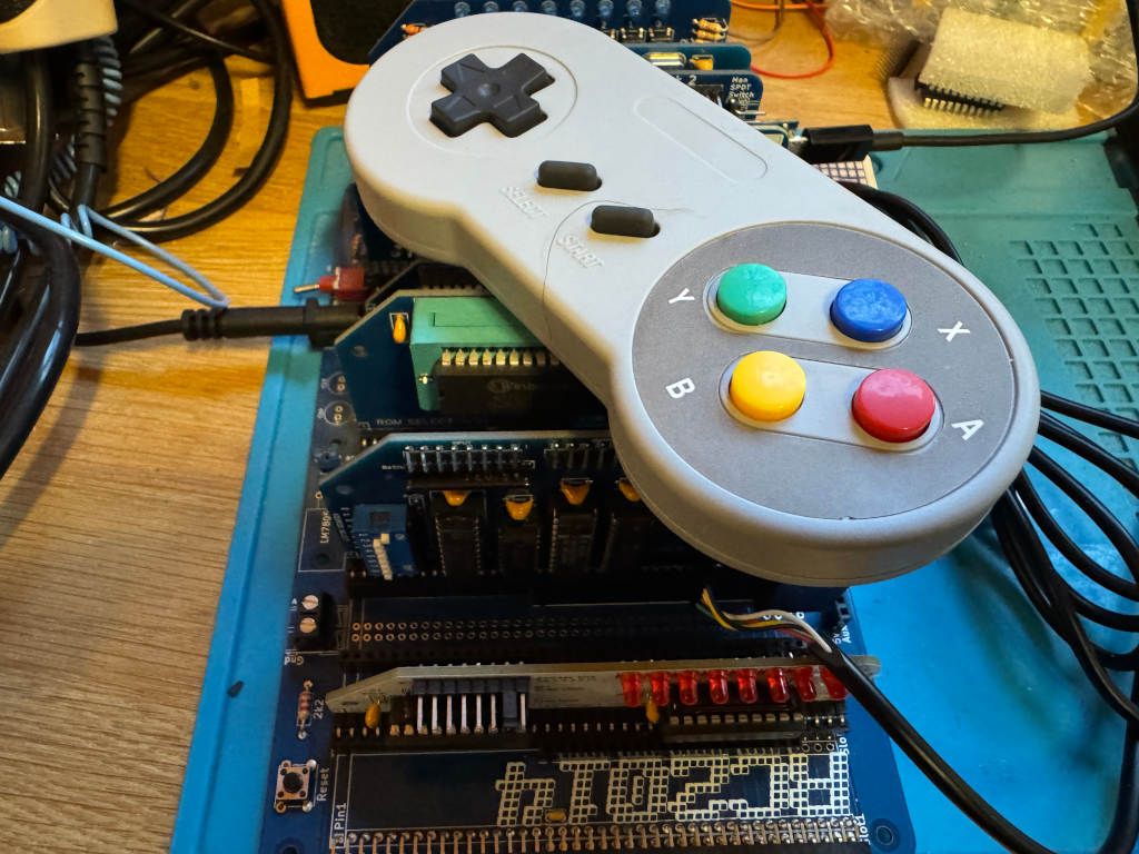
Chartreuse on Mastodon pointed out that the SNES controller is quite like the NES controller. Instead of returning a single byte, it returns two bytes. The first byte is the same as the NES controller; the second contains extra buttons.

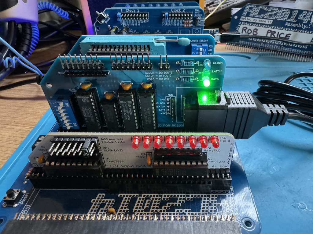
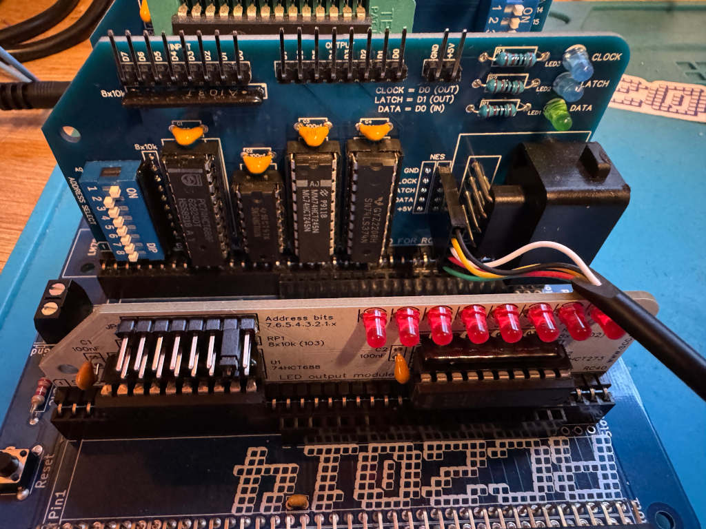
I wanted to see if my existing work could be easily extended to use a SNES controller, so I bought one on AliExpress. I also bought a SNES extension lead so I could cut it in half and add Dupont sockets to the wires. This means I could wire it directly to the RC2014 module I designed for the NES controller using one of the debug connectors I added to the PCB.

The SNES controller uses a different connector, but the pins work in the same way. This diagram shows the 5 pins we are interested in, and how we need to wire them up to the RC2014 NES controller module.

The pinout of a SNES controller
The SNES cable wired up via dupont connectors to the RC2014

Writing a reusable Z80 routine

As there are two bytes being returned, I can’t just call my get_buttons routine. This will toggle the Latch twice, so I will never get the extra buttons.

Instead, I have to toggle Latch one at the start of the routine, and call a cut down version of the original get_buttons routine that reads the 8 bits twice. The first byte returned will be the original NES buttons. The second byte will be the extra buttons on the SNES controller. Instead of returning a single byte in register a, I will instead use register pair de. Register d will hold the NES button data, and register e will hold the SNES button data.

; SNESController.inc
; Definitions and subroutine to read SNES controller button states
; Robert Price - 1st November 2025


; The Z80 port address to use for the controller interface.
NES_PORT    EQU $01

; The bit masks for the controller interface lines.
CLOCK   EQU $01
LATCH   EQU $02
DATA    EQU $01


; subroutine to read the NES controller button states.
; returns the button states in DE registers.
; register D contains the high byte, and register E the low byte. 
; All other registers are preserved.
; The high byte is like the NES controller, low has the extra SNES buttons.
get_buttons:
        push af           ; save af registers
        push bc           ; save bc registers

; pulse the LATCH line low to high and back to low again.
        xor a               ; set a to 0 
        out (NES_PORT), a
        ld a, LATCH
        out (NES_PORT), a
        xor a               ; set a to 0
        out (NES_PORT), a

        call .get_buttons
        ld d, a             ; store the button states in register d
        call .get_buttons
        ld e, a             ; store the button states in register e

        pop bc              ; restore bc registers
        pop af              ; restore af registers

        ret                 ; return to caller with button states in a


.get_buttons:
; setup the loop counter to read 8 buttons.
        ld b, 8             ; 8 buttons to read. 

; now we rebuild the byte into register c. As we are setting all 8 bits,
; we don't need to worry about clearing c first.
.loop:
; read the controller button states
        in a, (NES_PORT)    ; read the DATA line

; move the DATA bit into register c to rebuild the send byte
        srl a               ; shift right to get the DATA bit into carry
        rr c                ; rotate carry into bit 7 of c

; pulse the CLOCK line to read the next button.
        ld a, CLOCK
        out (NES_PORT), a
        xor a               ; set a to 0
        out (NES_PORT), a

; loop to read all buttons.
        djnz .loop

; return the button states in register a
        ld a, c             ; put the final button states in a 
        ret

Using the new Z80 routine

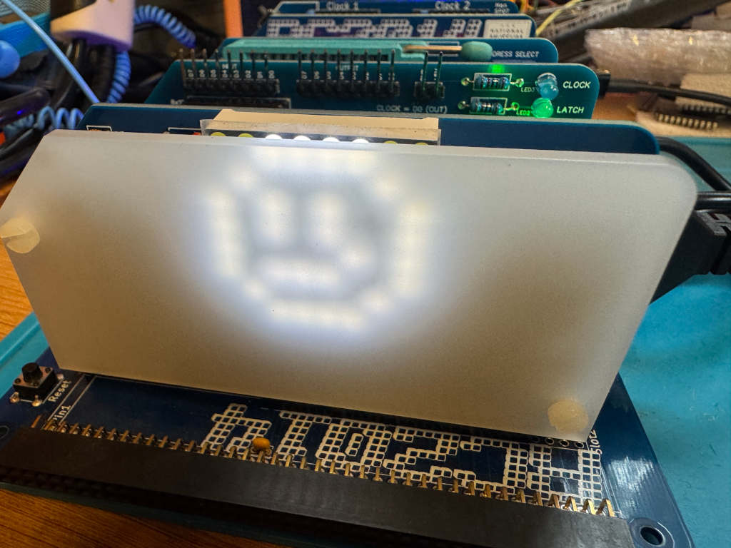
To test the new routine, I can use LEDs as before. I have two modules that can display an 8-bit value using LEDs. A RC2014 Digital IO module at IO address 0, and a SC134 module at IO address 2. I will display one returned byte on one of the modules, and the second returned byte on the other module. This can be run using SCM as before.

 ; A simple button reading program for the RC2014 Z80 computer running SCM
 ; this version outputs the SNES button states to a LED output
 ; Robert Price - 1st November 2025

        ORG $9000

; the Z80 port address to use for the LED output.
; This expects two Digital IO ports to be connected to the RC2014,
; one at IO address 0 for the high byte, and one at IO address 2 for the low byte.
LED_PORT_H  EQU $00
LED_PORT_L  EQU $02

main:
; get the button states from the SNES controller
        call get_buttons     ; call the get_buttons subroutine
        ld a, d              ; get the high byte button states
        cpl                  ; invert the bits in register a so pressed buttons are 1, and unpressed are 0
        out (LED_PORT_H), a  ; output the button states to the LED port

        ld a, e              ; get the low byte button states
        cpl                  ; invert the bits in register a so pressed buttons are 1, and unpressed are 0
        out (LED_PORT_L), a  ; output the button states to the LED port

        jr main              ; repeat forever

        INCLUDE "SNESController.inc"

        END

RC2025 – Part 8 – Playing Manic Miner with an NES controller

I’ve made good progress with my RetroChallenge to get an NES controller working on my RC2014 computer.

I wanted to be able to play a game with the controller. I had hoped to write my own, but with only a few days left, I didn’t think this was practical. Instead, I wondered about hacking an existing game.

While it’s not an RC2014, the Sinclair ZX Spectrum is also based on the Z80 processor. Colin Piggot makes a ZX Spectrum Bus Interface that allows RC2014 cards to be plugged into a Speccy.

As the RC2014 NES controller module can now be plugged into a Speccy, could I adapt one of my favourite games to work with it? Could Manic Miner be playable with an NES controller?

The Manic Miner intro screen.

The first step was to try to disassemble Manic Miner to see how the existing Kempston joystick support worked. I was hoping it would be simple to just wire in NES controller support there.

I made a start on this myself, before thinking that for such an iconic game, someone must have done this before. A quick search revealed an excellent commented disassembly of Manic Miner by Richard Dymond.

Faking a Kempston joystick

The Kempston joystick interface works by using a Z80 in operation on port 31. I would need to fake this by calling a routine to read the NES controller and return data in the Kempston format.

The Kempston joysticker interface returns the following in a single byte.

BitValue
0Right
1Left
2Down
3Up
4Fire
5N/A
6N/A
7N/A

So, if the Fire button is being pressed, bit 4 will be 1.

I can modify the get_buttons routine I previously wrote to read the NES controller and return the data in this format.

To do this, before the pop bc instruction, I can add the following code.

; build the kempston joystick byte in register a
        xor a               ; clear a
        
.test_fire:
        bit NES_A_BTN, c
        jr nz, .test_up
        set 4, a
.test_up:
        bit NES_UP_BTN, c
        jr nz, .test_down
        set 3, a
.test_down:
        bit NES_DOWN_BTN, c
        jr nz, .test_left
        set 2, a
.test_left:
        bit NES_LEFT_BTN, c
        jr nz, .test_right
        set 1, a
.test_right:
        bit NES_RIGHT_BTN, c
        jr nz, .done
        set 0, a
.done:
        pop bc              ; restore bc registers

Here I am clearing the a register so all bits have a default value of 0. Next, I am testing the bits in the byte I built to store the values from the NES controller. If the bits are set in the NES byte, then I set the relevant bit in the Kempston byte.

Hacking Manic Miner

My original idea was to load Manic Miner into a Spectrum, then use a Multiface to poke my changes into memory. Although this would work, I decided it would take too long and would be harder to save my work.

Instead, I downloaded a clean .tap file of Manic Miner from World of Spectrum and loaded this into the ZEsarUX emulator. ZEsarUX will let me poke my changes into the game and save the results as an SNA file. I can use the SNA file on a DivMMC connected to my Spectrum to load the game. This means I can make sure the game is still working before saving my changes.

I needed to find a place to store my get_buttons routine in Manic Miner. Upon examining the disassembly, remnants of the source code from when Matthew Smith was writing the game are visible at 0x934c. This space is unused in the game, so it’s safe for me to put my code there.

; A simple button reading program for the RC2014 Z80 computer running SCM
; This will pretend to be a Kempston joystick interface, and return bits like that interface.
; Robert Price - 24th October 2025

        ORG $934c

; The Z80 port address to use for the controller interface.
NES_PORT    EQU $01

; The bit masks for the controller interface lines.
CLOCK   EQU $01
LATCH   EQU $02
DATA    EQU $01

NES_A_BTN      EQU $00
NES_UP_BTN     EQU $04
NES_DOWN_BTN   EQU $05
NES_LEFT_BTN   EQU $06
NES_RIGHT_BTN  EQU $07


; subroutine to read the NES controller button states.
; returns the button states in register a.
; all other registers are preserved.
get_buttons:
        push bc           ; save bc registers

; pulse the LATCH line low to high and back to low again.
        xor a               ; set a to 0 
        out (NES_PORT), a
        ld a, LATCH
        out (NES_PORT), a
        xor a               ; set a to 0
        out (NES_PORT), a

; setup the loop counter to read 8 buttons.
        ld b, 8             ; 8 buttons to read. This will be decremented to 0.

; now we rebuild the byte into register c. As we are setting all 8 bits,
; we don't need to worry about clearing c first.
.loop:
; read the controller button states
        in a, (NES_PORT)    ; read the DATA line

; move the DATA bit into register c to rebuild the send byte
        srl a               ; shift right to get the DATA bit into carry
        rr c                ; rotate carry into bit 7 of c

; pulse the CLOCK line to read the next button.
        ld a, CLOCK
        out (NES_PORT), a
        xor a               ; set a to 0
        out (NES_PORT), a

; loop 8 times to read all buttons.
        djnz .loop

; build the kempston joystick byte in register a
        xor a               ; clear a
        
.test_fire:
        bit NES_A_BTN, c
        jr nz, .test_up
        set 4, a
.test_up:
        bit NES_UP_BTN, c
        jr nz, .test_down
        set 3, a
.test_down:
        bit NES_DOWN_BTN, c
        jr nz, .test_left
        set 2, a
.test_left:
        bit NES_LEFT_BTN, c
        jr nz, .test_right
        set 1, a
.test_right:
        bit NES_RIGHT_BTN, c
        jr nz, .done
        set 0, a
.done:
        pop bc              ; restore bc registers

        ret                 ; return to caller with button states in a

I compiled the code using the sjasmplus assembler on my Mac, and this gave me a 61-byte block of assembled code. Running this through hexdump gave me the following hex code to poke into memory.

9c4c  c5 af d3 01 3e 02 d3 01  af d3 01 06 08 db 01 cb
9c5c  3f cb 19 3e 01 d3 01 af  d3 01 10 f1 af cb 41 20
9c6c  02 cb e7 cb 61 20 02 cb  df cb 69 20 02 cb d7 cb
9c7c  71 20 02 cb cf cb 79 20  02 cb c7 c1 c9

I used the Hexadecimal Editor in the Debug Menu of ZEsarUX to input this.

Now I needed to call this when the Kempston joystick was being called from the game.

The first place this is done is at address 0x8878. This code checks if the fire button is being pressed in demo mode.

8878	LD A,($8459)	Pick up the Kempston joystick indicator from 8459
887B	OR A	        Is there a joystick connected?
887C	JR Z,$8884	Jump if not
887E	IN A,($1F)	Collect input from the joystick

In this case, I don’t need to check the joystick indicator, so all 4 instructions can be replaced with the following.

8878    CALL $934C
887B    NOP
887C    NOP
887D    NOP
887E    NOP
887F    NOP

The NOP instructions tell the Z80 to do nothing. I am just using them to fill up the space that the 4 original instructions were using. The assembled code looks like this, and it was loaded using the hexadecimal editor.

8878  cd 4c 93 00 00 00 00 00

The next block of code looks for left or right being pressed at address 0x8C24

8C24	LD A,($8459)	Collect the Kempston joystick indicator from 8459
8C27	OR A	        Is the joystick connected?
8C28	JR Z,$8C34	Jump if not
8C2A	LD BC,$001F	Collect input from the joystick
8C2D	IN A,(C)

I can use the same code as before to drop in there, but I need an extra 3 NOP instructions to fill up the space. The replacement hex code looks like this.

8C24  cd 4c 93 00 00 00 00 00 00 00 00

There is similar code to check the fire button at address 0x8c6c. I can poke in the same hex code there.

8C6C  cd 4c 93 00 00 00 00 00 00 00 00

Finally, there is a routine at 0x9337 that checks if the fire button is being pressed. This is a shorter version like the code at 0x8878, so I can poke in the same code there.

9337  cd 4c 93 00 00 00 00 00

I can now save a snapshot of the game. I do this using the Snapshot option in ZEsarUX and making sure I use a .SNA file extension. I called my file MMNES.SNA. It’s available to download for anyone following along.

Copying this to an SD card and placing it in the DivMMC allowed me to load the modified game on my Spectrum.

A screenshot of Manic Miner's first level - The Central Cavern

Conclusion

While I hadn’t planned to hack a Spectrum game as part of the RetroChallenge this year, it’s turned out to be a great diversion and learning experience. It’s still using the code and hardware developed on the RC2014.

The joypad works well, and although it is using a little more CPU time, it’s not noticeable when playing the game. It doesn’t have the nostalgia value of using the Spectrum’s rubber keys, but it is responsive and comfortable to use.

The NES Controller module connected to a Spectrum with the Quazar bus interface.

RC2025 – Part 7 – Moving a pixel with a NES controller

In previous posts, I’ve covered how to read an NES controller from an RC2014 computer, and also how to use an 8×8 LED matrix. I now want to combine these and use the NES controller to move a pixel on the LED matrix.

The first thing we want to do is to draw a pixel in the top left corner of the LED matrix. To do this, I’ll use register b for the Row data and register c for the Column data. We need to set a single bit in each because we only want a single pixel lit.

        ORG $9000

ROW     EQU 0
COLUMN  EQU 2

setup:
        ld b, 0b00000001  ; Row bit for the pixel
        ld c, 0b10000000  ; Column bit for the pixel

main:

.draw_pixel:
        xor a             ; clear a
        out (COLUMN), a   ; clear the columns
        ld a, b           ; get the current row bit
        out (ROW), a      ; select the row
        ld a, c           ; get the column data for this row
        out (COLUMN), a   ; output the column data

        jr main           ; repeat forever

        END

Now that we have a pixel, we need to read the NES controller and react to movement on the joypad.

We can use Z80 rlc and rrc operations to move the single bit to the left or right in the Row and Column registers. If we reach the end of the byte, the bit will roll over to the other end of the byte.

To test which button is being pressed, we can use a bit operation. If the button isn’t being pressed, we can jump ahead to test the next button.

In our main loop, we can add the following.

UP_BTN   EQU $04
DOWN_BTN EQU $05
LEFT_BTN EQU $06
RIGHT_BTN EQU $07

main:
        call get_buttons   ; Get NES controller button states in A

.test_left:
        bit LEFT_BTN, a
        jr nz, .test_right
        rlc c
.test_right:
        bit RIGHT_BTN, a
        jr nz, .test_up
        rrc c
.test_up:
        bit UP_BTN, a
        jr nz, .test_down
        rrc b
.test_down:
        bit DOWN_BTN, a
        jr nz, .draw_pixel
        rlc b

.draw_pixel:

We also need to include the get_buttons routine we previously wrote. This returns the buttons being pressed on the NES controller in register a.

        INCLUDE "NESController.inc"

        END

At the moment, this is executing far too fast, so we end up with an entire row or column being lit. We need to add a delay. We can write a very simple Z80 routine to just loop X times as a simple delay.

delay:
        ld de, 50000
.delay_loop:
        dec de
        ld a, d
        or e
        jr nz, .delay_loop
        ret

The final working code

Putting this all together, we end up with the following code…


; A simple program to move a pixel on an 8x8 LED matrix
; connected to the RC2014 Z80 computer.
; Robert Price - 19th October 2025

        ORG $9000

ROW     EQU 0
COLUMN  EQU 2

UP_BTN   EQU $04
DOWN_BTN EQU $05
LEFT_BTN EQU $06
RIGHT_BTN EQU $07

setup:
        ld b, 0b00000001  ; Row bit for the pixel
        ld c, 0b10000000  ; Column bit for the pixel

main:
        call get_buttons   ; Get NES controller button states in A

.test_left:
        bit LEFT_BTN, a
        jr nz, .test_right
        rlc c
.test_right:
        bit RIGHT_BTN, a
        jr nz, .test_up
        rrc c
.test_up:
        bit UP_BTN, a
        jr nz, .test_down
        rrc b
.test_down:
        bit DOWN_BTN, a
        jr nz, .draw_pixel
        rlc b

.draw_pixel:
        xor a             ; clear a
        out (COLUMN), a   ; clear the columns
        ld a, b           ; get the current row bit
        out (ROW), a      ; select the row
        ld a, c           ; get the column data for this row
        out (COLUMN), a   ; output the column data

        call delay        ; small delay to make movement visible

        jr main           ; repeat forever

delay:
        ld de, 50000
.delay_loop:
        dec de
        ld a, d
        or e
        jr nz, .delay_loop
        ret

        INCLUDE "NESController.inc"

        END

Here is a video of the code in action.

RC2025 – Part 6 – Using an 8×8 LED matrix from Z80 assembly language

As part of the 2025 RetroChallenge I’ve been developing an NES controller module for the RC2014 computer.

Up until now, I’ve just been outputting to a terminal. However, I’d like to use something a bit more visual on the RC2014. I’ve decided to use Peacock Media’s 8×8 LED matrix module for this.

The module works by outputting an 8-bit value to one IO port for the row and another 8-bit value to another IO port for the column. These describe which LEDs should be enabled. Each bit in the byte refers to either a row or a column.

The default IO port for the row is 0, and the default IO port for the column is 2.

If I want the top left corner to light, I need to set bit 8 of the column and bit 1 of the row.

If you have the SCM (Small Computer Monitor) program running on an RC2014, you can quickly test it out using the following.

o 0 1
o 2 80

This sets the row to hexadecimal 1, which in binary is 00000001, and the column to hexadecimal 80 which in binary is 1000000.

A smiley face in BASIC

In the documentation for the 8×8 module, Shelia Dixon gives us an example BASIC program to draw a smiley face.

This works by rapidly updating the pixels rather than keeping them permanently on. Repeated fast enough, persistence of vision makes the LEDs appear to be on constantly.

10 FOR I=0 TO 7
20 READ R,C
30 OUT 2,0 : OUT 0,R : OUT 2,C
40 NEXT I
50 RESTORE
60 GOTO 10
1000 DATA 1,60, 2,66, 4,169, 8,169
1010 DATA 16,133, 32,185, 64,66, 128,60

A smiley face in Z80 assembly language

I wanted to convert the BASIC program to Z80 assembly language to help me better understand how this works.

I take a similar approach to the BASIC program. I iterate over a loop 8 times to represent the current Row. I keep this counter in register b. In register c, I keep the current bit the row is pointing to. In each iteration, I read a byte of data from memory that represents the Column. The position in memory is pointed to by register pair hl. Once the data has been output, I then shift the value in register c to the right so it points to the next row.

The final code looks like this.


; A simple program to display a smiley face on an 8x8 LED matrix
; connected to the RC2014 Z80 computer.
; Robert Price - 19th October 2025
;
; Based on the original BASIC example by Shiela Dixon
        ORG $9000

ROW     EQU 0
COLUMN  EQU 2

main:
        ld b, 8           ; 8 rows to display
        ld c, 0b10000000  ; start with bit 7 set for row 8
        ld hl, data       ; point to the smiley data
.loop:
        xor a             ; clear a
        out (COLUMN), a   ; clear the columns
        ld a, c           ; get the current row bit
        out (ROW), a      ; select the row
        ld a, (hl)        ; get the column data for this row
        out (COLUMN), a   ; output the column data
        inc hl            ; point to next row data
        srl c             ; shift to next row bit
        djnz .loop        ; loop for all 8 rows        

        jr main           ; repeat forever

data:
        db 0b00111100     ; 60
        db 0b01000010     ; 66
        db 0b10111001     ; 185
        db 0b10000101     ; 133
        db 0b10101001     ; 169
        db 0b10101001     ; 169
        db 0b01000010     ; 66  
        db 0b00111100     ; 60

        END

RC2025 – Part 5 – Writing a reusable Z80 subroutine to read the NES controller

I wanted to write a reusable Z80 assembly language subroutine to read the NES controller and return the status of the buttons in a register.

The principle is the same as my previous posts in that I have to pulse the Latch and Clock lines, and read data 1 bit at a time from the Data line. However, this time I want to store all 8 returned bits in a single byte that I can return in a register.

I had some feedback from Jon Jones on Bluesky who suggested I could optimise my previous code by replacing the ld a,0 instruction with xor a. This is a byte smaller, and is quite a neat trick as a value exclusive or’d with itself will always be 0.

I have also been learning more about how shifting and rotating works on the Z80. When I read my bit from the data line, if I use a slr a instruction, it will push the bit that has just been read onto the carry flag. I can then use rr c to move the contents of register c one to the right and fill bit 7 with the contents of the carry flag. Doing this 8 times will fill the c register with all the values I need.

The finished subroutine looks like this.

; NESController.inc
; Definitions and subroutine to read NES controller button states
; Robert Price - 19th October 2025


; The Z80 port address to use for the controller interface.
NES_PORT    EQU $01

; The bit masks for the controller interface lines.
CLOCK   EQU $01
LATCH   EQU $02
DATA    EQU $01


; subroutine to read the NES controller button states.
; returns the button states in register a.
; all other registers are preserved.
get_buttons:
        push bc           ; save bc registers

; pulse the LATCH line low to high and back to low again.
        xor a               ; set a to 0 
        out (NES_PORT), a
        ld a, LATCH
        out (NES_PORT), a
        xor a               ; set a to 0
        out (NES_PORT), a

; setup the loop counter to read 8 buttons.
        ld b, 8             ; 8 buttons to read. This will be decremented to 0.

; now we rebuild the byte into register c. As we are setting all 8 bits,
; we don't need to worry about clearing c first.
.loop:
; read the controller button states
        in a, (NES_PORT)    ; read the DATA line

; move the DATA bit into register c to rebuild the send byte
        srl a               ; shift right to get the DATA bit into carry
        rr c                ; rotate carry into bit 7 of c

; pulse the CLOCK line to read the next button.
        ld a, CLOCK
        out (NES_PORT), a
        xor a               ; set a to 0
        out (NES_PORT), a

; loop 8 times to read all buttons.
        djnz .loop

; return the button states in register a
        ld a, c             ; put the final button states in a 

        pop bc              ; restore bc registers

        ret                 ; return to caller with button states in a

Testing the subroutine

To test the new subroutine I made use of the SC134 LED output card I was kindly given at RC2014 Assembly. The standard RC2014 Digital IO card will also work. I have assigned this to IO address 2.

The code simply reads the NES controller, inverts the bits using the cpl instruction, outputs the value to the LEDs, and loops.

I need to use the cpl instruction as the NES controller returns a pressed button as 0. If I didn’t do this, the LEDs would be on apart from any button being pressed. cpl inverts all the bits in the a register so any button being pressed is now lit.

; the Z80 port address to use for the LED output.
LED_PORT    EQU $02

main:
; get the button states from the NES controller
        call get_buttons     ; call the get_buttons subroutine
        cpl                  ; invert the bits in register a so pressed buttons are 1, and unpressed are 0
        out (LED_PORT), a    ; output the button states to the LED port
        jr main              ; repeat forever

Here is a video of the code in action.

RC2025 – Part 4 – Bit-banging a NES controller using Z80 assembly language

In my last post, I wrote about using MS-Basic on my RC2014 to bit-bang an NES controller. In this post, I want to use Z80 assembly language to do the same. I want to be able to press a button on the controller and have its name printed on the serial terminal.

The first thing we need to do is set up a few things.

The code will need to run at 0x9000, so an ORG statement will tell the assembler to build the code to run from there.

        ORG $9000

The NES controller module will be located at the Z80 IO port 1.

PORT    EQU $01

The Clock bit is 1, the Latch bit is 2, and the Data bit is 1.

CLOCK   EQU $01
LATCH   EQU $02
DATA    EQU $01

I’ll be using Stephen Cousins’ SCM on the RC2014. The SCM API provides a routine to print a string, so I’ll be using that later on. This is API call 0x06.

OUTPUT_LINE EQU $06

The first thing the code will need to do is to pulse the Latch line low, high, low. This will capture the current state of the buttons being pressed on the NES controller.

start:
        ld a, 0
        out (PORT), a
        ld a, LATCH
        out (PORT), a
        ld a, 0
        out (PORT), a

Now we need to loop 8 times to capture each of the 8 bits the NES controller is going to be sending us.

        ld b, 8 
loop:
        djnz loop

Inside the loop, we first need to read the Data line to get the current bit. We mask out all but the Data bit and then see if it is 0 or not. If it’s not zero, skip the next block of code.

        in a, (PORT)

        and DATA
        jr nz, .skip

If a button is being pressed, we need to look up the name of the button in a lookup table and print it out using the SCM API. To do this, we get the current iteration minus 1 and store it in the HL register. As this is a 16 bit register, we need to set the L register to the iteration value, and H to 0. We add this value to the address of the lookup table to get the address of the string to print. We then pass this to the SCM API.

        ld de, lookuptable  ; point to the lookup table
        ld a, b             ; put the current iteration from b into a
        dec a               ; delete 1 to make it zero based
        ld l, a             ; place the interation in l
        ld h, 0             ; zero h, hl should now be value of the iteration
        add hl, hl          ; multiply by 2 (size of address)
        add hl, de          ; add to base address of table
        ld e, (hl)          ; get low byte of string address to use
        inc hl              ; point to high byte
        ld d, (hl)          ; get high byte of string address
        ld c, OUTPUT_LINE   ; SCM output line
        push bc             ; save the bc registers to the stack
        rst $30             ; Call SCM API
        pop bc              ; restore the bc registers from the stack
lookuptable:
        dw right_txt
        dw left_txt
        dw down_txt
        dw up_txt
        dw start_txt
        dw select_txt
        dw b_txt
        dw a_txt

a_txt:      db "A",5,0
b_txt:      db "B",5,0
select_txt: db "Select",5,0
start_txt:  db "Start",5,0
up_txt:     db "Up",5,0
down_txt:   db "Down",5,0
left_txt:   db "Left",5,0
right_txt:  db "Right",5,0

Next, we pulse the CLOCK line high to low before we end the loop.

.skip:
        ld a, CLOCK
        out (PORT), a
        ld a, 0
        out (PORT), a

Finally, we loop back to the very start of the program.

        jr start

The complete Z80 assembly language program

Here’s the code as a single program that can be assembled using the sjasmplus assembler.

 ; A simple button reading program for the RC2014 Z80 computer running SCM
 ; Robert Price - 15th October 2025

        ORG $9000

; The Z80 port address to use for the controller interface.
PORT    EQU $01

; The bit masks for the controller interface lines.
CLOCK   EQU $01
LATCH   EQU $02
DATA    EQU $01

; The SCM API value to output a line.
OUTPUT_LINE EQU $06

start:
; pulse the LATCH line low to high and back to low again.
        ld a, 0
        out (PORT), a
        ld a, LATCH
        out (PORT), a
        ld a, 0
        out (PORT), a

; setup the loop counter to read 8 buttons.
        ld b, 8             ; 8 buttons to read. This will be decremented to 0.
loop:
; read the controller button states
        in a, (PORT)        ; read the DATA line

        and DATA            ; mask out all but DATA bit
        jr nz, .skip        ; skip if a button was not pressed

; print out the button pressed using a lookup table.
        ld de, lookuptable  ; point to the lookup table
        ld a, b             ; put the current iteration from b into a
        dec a               ; delete 1 to make it zero based
        ld l, a             ; place the interation in l
        ld h, 0             ; zero h, hl should now be value of the iteration
        add hl, hl          ; multiply by 2 (size of address)
        add hl, de          ; add to base address of table
        ld e, (hl)          ; get low byte of string address to use
        inc hl              ; point to high byte
        ld d, (hl)          ; get high byte of string address
        ld c, OUTPUT_LINE   ; SCM output line
        push bc             ; save the bc registers to the stack
        rst $30             ; Call SCM API
        pop bc              ; restore the bc registers from the stack

.skip:
; pulse the CLOCK line to read the next button.
        ld a, CLOCK
        out (PORT), a
        ld a, 0
        out (PORT), a

; loop 8 times to read all buttons.
        djnz loop

; forever loop to read buttons again.
        jr start


; the lookup table stores the addresses of the text strings for each button.
lookuptable:
        dw right_txt
        dw left_txt
        dw down_txt
        dw up_txt
        dw start_txt
        dw select_txt
        dw b_txt
        dw a_txt

; The text strings to print for each button.
; each string is terminated with a CR (5) and a null (0).
a_txt:      db "A",5,0
b_txt:      db "B",5,0
select_txt: db "Select",5,0
start_txt:  db "Start",5,0
up_txt:     db "Up",5,0
down_txt:   db "Down",5,0
left_txt:   db "Left",5,0
right_txt:  db "Right",5,0

Once assembled, I convert it to Intel Hex using z88dk-appmake and send it to my RC2014 running SCM. It is then executed using g 9000 .

It is very fast code, so even the slightest tap of a button will register multiple times.

RC2025 – Part 3 – Bit-banging a NES controller from BASIC

In my earlier articles, I’ve written about how an NES controller works and designed some hardware for the RC2014 to talk to one.

Since then, my PCBs have arrived, and I’ve built the RC2014 module. I had to cut the track from RESET I was using to enable one of the chips and wire that to GND. I explained why in my previous post.

RC2014 NES Controller module with bodge wire in place

I’ve given the module IO address 1 using the jumper switches. This means I can talk to it using the MS-Basic commands OUT 1,X for output, and INP(1) for input.

RC2014 NES Controller module plugged into an RC2014 Picasso

As the output from the NES controller is active low, the green LED attached to the Data input is lit unless a button is being pressed. I should probably have wired this so it only lights if a button is being pressed. This is just a cosmetic issue.

First BASIC program

The first thing I need to do to talk to the NES controller is to toggle the Latch line. This is D1. I need to make this go from low to high, then back to low.

Next, I need to iterate the following 8 times, 1 for each bit. Read the input and toggle the Clock line high to low to get the next bit ready. If I see a zero value on my input, I know a button has been pressed.

Finally, I restart the program from the beginning.

10 REM Bit Banging an NES Controller from an RC2014.
11 REM Robert Price - October 2025.
20 REM First we toggle the Latch line on D1. 
30 OUT 1,0
40 OUT 1,2
50 OUT 1,0
60 REM Iterate 8 times to get all 8 bits.
70 FOR I=0 TO 7
80 REM Get the current bit in D0.
90 LET A= INP(1)
100 REM Toggle the Clock line in D0.
110 OUT 1,1
120 OUT 1,0
130 REM If we have a non zero value, then a button has been pressed.
140 IF A=0 THEN PRINT I
150 NEXT I
160 REM loop back to the beginning.
170 GOTO 10

When I run this code and press a button, the value of I is printed on the terminal.

Improving the BASIC program

Instead of just printing a numeric value, I can print the name of the button being pressed. In my earlier article, I listed what these values were. To do this, I look at the value of variable I, and print what that value actually means.

10 REM Bit Banging an NES Controller from an RC2014.
11 REM Robert Price - October 2025.
20 REM First we toggle the Latch line on D1. 
30 OUT 1,0
40 OUT 1,2
50 OUT 1,0
60 REM Iterate 8 times to get all 8 bits.
70 FOR I=0 TO 7
80 REM Get the current bit in D0.
90 LET A= INP(1)
100 REM Toggle the Clock line in D0.
110 OUT 1,1
120 OUT 1,0
130 REM If we have a non zero value, then a button has been pressed.
140 IF A<>0 THEN GOTO 230
150 IF I=0 THEN PRINT "A"
160 IF I=1 THEN PRINT "B"
170 IF I=2 THEN PRINT "SELECT"
180 IF I=3 THEN PRINT "START"
190 IF I=4 THEN PRINT "UP"
200 IF I=5 THEN PRINT "DOWN"
210 IF I=6 THEN PRINT "LEFT"
220 IF I=7 THEN PRINT "RIGHT" 
230 NEXT I
240 REM loop back to the beginning.
250 GOTO 10

Running this and pressing a button now prints the name of that button to the terminal.

RC2025 – Part 2 – Designing a PCB for bit-banging a NES controller

In the first part of my RetroChallenge, I ended by saying I was planning to bit-bang the data from the NES controller into my RC2014.

Now it’s time to design a PCB to let me connect the NES controller to the RC2014.

I’m going to use Z80 IO, but I’m not sure what address yet. I’m going to use a 74HCT688 8-bit comparator to allow myself the ability to select a specific IO port on the Z80. I will use a DIP switch with pull-down resistors so I can change the IO port at will without having to get a new PCB made. The /IORQ line from the Z80 will be used to enable the 74HCT688.

I need to send Clock and Latch signals to the NES controller, so I need a way to output data on the Z80 IO port. I will use a 74HCT374 to do this. This will allow me to buffer the data lines from Z80. I will enable output by using a 74HCT02 and NORing the output from the 74HCT688 and the Z80 /WR line.

For reading data back to the Z80, I will use a 74HCT245. This will let me put data onto the databus when the correct IO Port is being read. I will use the 74HCT02 to NOR the output of 74HCT688 and the Z80 /RD line to enable the chip. However, this needs to be inverted to work, so I will just use another NOR gate as a NOT gate to do this.

I will add LEDs on the input and output lines to the NES controller socket to help with any debugging I may need to do. I will also add plenty of test points to see what is going on during debugging. As there are plenty of unused input and output pins, I will expose these on headers for possible future use.

Bit-banging PCB for the NES controller on an RC2014

I have decided to use the following pins to talk to the NES controller.

PINREAD / WRITENES
D0READDATA
D0WRITECLOCK
D1WRITELATCH

Laying out the PCB

I have laid out the PCB using Spencer Owen’s guidelines for RC2014 modules.

The spare output pins have been placed at the top for easy access. The NES controller socket has been placed on the right-hand side, along with the test points for it. The indicator LEDs have been placed above this for visibility.

I have added a ground plane to the back of the PCB, and let EasyEDA handle the routing for me.

PCB layout for the NES controller module

You may have noticed that the diagram is for revision 1.1 of the circuit. 1.0 was essentially the same, but I had the output enable on the 74HCT374 connected to the Z80 /RST line. The idea being I only want this to present data on the bus if the Z80 wasn’t being reset. This pin is only low on reset, so data was never being presented. I just tied this to GND in revision 1.1.

Unfortunately, revision 1.0 is the version I sent off to be manufactured, so it will need a bodge when I come to solder up the PCB. The trace from /RST will need to be cut, and OE will need to be wired to GND.

RC2025 – Part 1 – How does the NES controller send data?

For this year’s RetroChallenge, I am hoping to interface an NES / Famicon controller to my RC2014 computer.

The NES controller has 8 buttons: Up, Down, Left, Right, Select, Start, A, and B.

The cable only has 7 pins, so how can it send up to 8 button presses using 7 wires?

Well, the NES controller only actually uses 5 of those wires. Two of those wires are GND and +5V. The other three are Latch, Clock, and Data.

A diagram of the NES controller port showing pin outs.

Inside the controller, there is a 4021 shift register. When the Latch is pulsed from high to low, the 4021 captures the state of the buttons in 8 bits. The first capture bit will then be placed on the Data line. When Clock is pulsed from high to low, the 4021 will then shift the internal data one place forward, and the next bit will be placed on the Data line. When the next Clock pulse arrives, the next bit is sent, and so on. This needs to happen 8 times until all 8 bits have been sent. A low bit on the Data line means the button has been pressed; otherwise, the bit will remain high.

The bits are sent in the following order.

BitButton
0A
1B
2Select
3Start
4Up
5Down
6Left
7Right

Using software bit-banging, I should be able to send the Latch and Clock signals, and reassemble the received 8 bits back into a single byte.

RC2025 – Taking part in RetroChallenge 2025

After taking part in the very enjoyable RetroChallenge in 2024, I’ve decided to take part again in 2025.

Last year, I worked on a rotary encoder module for the RC2014 computer.

This year, my plan is to interface a classic Nintento Entertainment System joypad to my RC2014.

There is already a module for reading Atari-style joysticks, but I don’t think there is anything for a NES controller.

There are 8 buttons on the NES controller, but the connector has only 7 pins. This means that there is something interesting going on, and it’s not just each button shorting one pin.