I wanted to write a reusable Z80 assembly language subroutine to read the NES controller and return the status of the buttons in a register.
The principle is the same as my previous posts in that I have to pulse the Latch and Clock lines, and read data 1 bit at a time from the Data line. However, this time I want to store all 8 returned bits in a single byte that I can return in a register.
I had some feedback from Jon Jones on Bluesky who suggested I could optimise my previous code by replacing the ld a,0 instruction with xor a. This is a byte smaller, and is quite a neat trick as a value exclusive or’d with itself will always be 0.
I have also been learning more about how shifting and rotating works on the Z80. When I read my bit from the data line, if I use a slr a instruction, it will push the bit that has just been read onto the carry flag. I can then use rr c to move the contents of register c one to the right and fill bit 7 with the contents of the carry flag. Doing this 8 times will fill the c register with all the values I need.
The finished subroutine looks like this.
; NESController.inc
; Definitions and subroutine to read NES controller button states
; Robert Price - 19th October 2025


; The Z80 port address to use for the controller interface.
NES_PORT    EQU $01

; The bit masks for the controller interface lines.
CLOCK   EQU $01
LATCH   EQU $02
DATA    EQU $01


; subroutine to read the NES controller button states.
; returns the button states in register a.
; all other registers are preserved.
get_buttons:
        push bc           ; save bc registers

; pulse the LATCH line low to high and back to low again.
        xor a               ; set a to 0
        out (NES_PORT), a
        ld a, LATCH
        out (NES_PORT), a
        xor a               ; set a to 0
        out (NES_PORT), a

; setup the loop counter to read 8 buttons.
        ld b, 8             ; 8 buttons to read. This will be decremented to 0.

; now we rebuild the byte into register c. As we are setting all 8 bits,
; we don't need to worry about clearing c first.
.loop:
; read the controller button states
        in a, (NES_PORT)    ; read the DATA line

; move the DATA bit into register c to rebuild the send byte
        srl a               ; shift right to get the DATA bit into carry
        rr c                ; rotate carry into bit 7 of c

; pulse the CLOCK line to read the next button.
        ld a, CLOCK
        out (NES_PORT), a
        xor a               ; set a to 0
        out (NES_PORT), a

; loop 8 times to read all buttons.
        djnz .loop

; return the button states in register a
        ld a, c             ; put the final button states in a

        pop bc              ; restore bc registers

        ret                 ; return to caller with button states in a
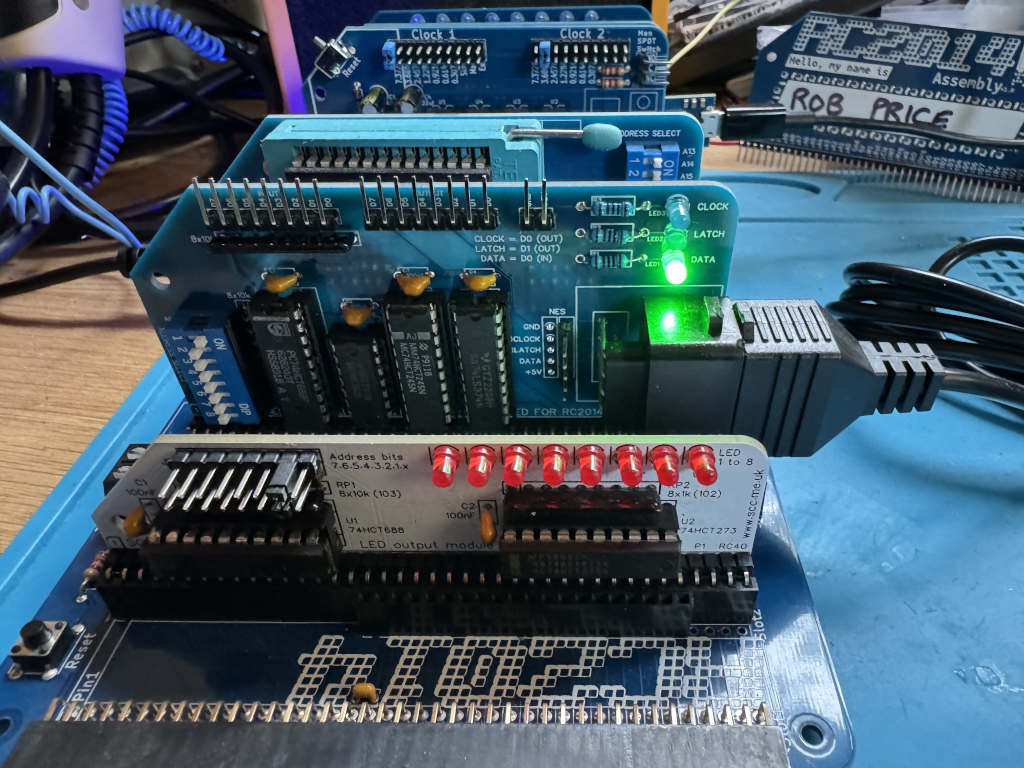
Testing the subroutine
To test the new subroutine I made use of the SC134 LED output card I was kindly given at RC2014 Assembly. The standard RC2014 Digital IO card will also work. I have assigned this to IO address 2.
The code simply reads the NES controller, inverts the bits using the cpl instruction, outputs the value to the LEDs, and loops.
I need to use the cpl instruction as the NES controller returns a pressed button as 0. If I didn’t do this, the LEDs would be on apart from any button being pressed. cpl inverts all the bits in the a register so any button being pressed is now lit.
; the Z80 port address to use for the LED output.
LED_PORT    EQU $02

main:
; get the button states from the NES controller
        call get_buttons     ; call the get_buttons subroutine
        cpl                  ; invert the bits in register a so pressed buttons are 1, and unpressed are 0
        out (LED_PORT), a    ; output the button states to the LED port
        jr main              ; repeat forever
Here is a video of the code in action.