One thing I really wanted to do as part of this year’s Retro Challenge was to build my first custom PCB for the RC2014 computer.
I have chosen to use EasyEDA to design my PCB. I was heavily influenced by watching James Sharman’s excellent YouTube videos in which he designs his own CPU using EasyEDA. The alternative was KiCad, which seems more complex for a beginner.
Spencer has kindly put the specifications for a RC2014 module template up on the RC2014 website. I will try to follow this when it comes to laying out my PCB.
The Circuit
The RC2014 Peripheral Addressing didn’t originally target exact addresses, instead it used 74LS138 chips to target ranges of addresses.
The SC219 takes a different approach, and uses a 74HCT688 8-Bit Magnitude Comparator to target a specific address. I think this is the best approach for my circuit. Using switches for the comparison will mean I can easily change the matched address if there are conflicts with any other cards on my RC2014. I will use the IORQ line from the RC2014 as the OE (Output Enable) line. I can take the output from the 74HCT688 and use a 74HCT32 OR Gate with the RD line to know when the peripheral address I want to respond to is being used. I will use a 74HCT245 Octal Bus Transceiver to present data on the data pins when active.
In my initial post I mentioned I had to use a 74HCT14 Schmitt Trigger to invert the input from the rotary encoder and help produce a cleaner digital signal. This will be connected to the 74HCT245’s D0 to D5 pins. This will allow me to support two rotary encoders, and leave D6 and D7 spare. I will provide two blocks of input pins, one block for each rotary encoder. Each of these will support the CLK, DT, and SW pins, as well as GND and +5V.
I will add some debugging support to the circuit. I like the input LEDs on the SC219 so I will also add these to my circuit so I can see the incoming data from the rotary encoders. I think a breakout of the incoming data lines before the 74HCT245 will be useful to see what is going on, and also allow the board to be used as an input device when the rotary encoders aren’t being used. Finally, I saw a discussion on one of the Sinclair Spectrum groups about adding a hook to GND to attach an oscilliscope to when debugging. This could be very useful if the circuit doesn’t work, so I will add in provision for this.
This is my initial design.
The PCB
As I mentioned earlier, there is a specification for the shape and size of PCBs for the RC2014.
Laying out the board I have tried to use EasyEDA’s measuring tool to ensure this is correct.
Adding the curved corner I found tricky, but eventually I was able to do this by targetting the BoardOutLine layer in EasyEDA.
I read on various forums that adding a ground plane to a PCB was a good idea, so I have done this on both the top and bottom layer of my PCB.
As my circuit is reasonably simple, I used EasyEDA’s auto routing functionality. This worked quickly and I didn’t need to do any manual routing.
For manufacturing I decided to use JLCPCB as EasyEDA has built in support for this manufacturer.
The board itself cost $3.20 for 5. I paid for express delivery because if I have made a mistake and need to create a new revision, it could take several weeks to arrive. The total for the 5 PCBs, delivery, and tax was £20.21. These are due for delivery on October 8th 2024.
JLCPCB adds a manufacturing code to each PCB. You can specify where this appears by adding the text “JLCJLCJLCJLC” to one of the silk layers. I put mine on the BottomSilkLayer so it’s not forward facing.
This is the final layout for my board. I can’t wait for it to arrive so I can solder it up and see if it works.
I now want to try reading it on the RC2014 and using it to control some output.
I’m using the SC219 Digital I/O Board on the RC2014 to accept inputs from a rotary encoder. I have mine mapped to I/O address port 0. Using Microsoft BASIC I can read this using the INP(0) statement. This will return a byte representing the values of D0 to D7 on the input port.
I am using D0 for the CLK, D1 for DT, and D2 for SW. D3 to D7 are not used at the moment. I am only interested in D0 and D1 for the rotary motion. I can use AND statements to mask bits when I’m checking the input value. So to check if D0 was 1 or 0, I could use INP(0) AND 1. This would return either 0 or 1. To check D1, I could use INP(0) AND 2. This would return either 0 or 2.
The following UML activity diagram shows at a high level how I need my BASIC program to operate.
The Microsoft BASIC on the RC2014 is old and limited compared to modern languages, but it is functional.
To save space, I’ll use variable A for CLK, and B for DT. I’ll need to keep track of the last state of A so I know when it has changed. To do this I’ll create a variable LAST_A. Finally, to keep track of the INP(0) result, I’ll create variable INPUT.
When I detect a change in A, I need to look to see if B matches A. If it does, then I know the encoder is being turned to the right. If it doesn’t, then it is being turned to the left.
Here is the BASIC code I came up with to do this. When it detects a change, it prints either “Left” or “Right” to the console.
10 LET LAST_A = 0
20 LET IN = INP(0)
30 LET A = IN AND 1
40 IF A = LASTA THEN GOTO 200
50 LET B = IN AND 2
60 IF (A=1 AND B=2) OR (B=0 AND A=0) THEN GOTO 100
80 PRINT "Right"
90 GOTO 200
100 PRINT "Left"
200 LET LAST_A = A
210 GOTO 20
The SC219 has digital outputs as well as inputs. Using the built-in output LEDs, I can move a dot left or right depending on the input from the rotary encoder.
The 8 output LEDs represent each bit of a byte. So we have the values 1, 2, 4, 8, 16, 32, 64, and 128 represented on bits D0 to D7. This is 2 to the power X, where X is between 0 and 7. We can use the ^ (power) operator in BASIC to help set these bits.
So we need to have a variable, let’s call it COUNTER, to keep track of which power we are currently at. We can say turning the rotary encoder left will increment COUNTER by 1. Turning the rotary encoderrigtht will decrement COUNTER by 1. We need some guards, so if COUNTER goes below 0, we set it to 7. If it goes above 7, we set it to 0. We set one of the LEDs by using OUT 0,2^COUNTER. This means when we turn the rotary encoder, we can move the LED.
Here is the BASIC code I wrote to do this.
10 LET COUNTER = 0
20 LET LAST_A = 0
30 LET IN = INP(0)
40 OUT 0,2^COUNTER
50 LET A = IN AND 1
60 IF A = LASTA THEN GOTO 200
70 LET B = IN AND 2
80 IF (A=1 AND B=2) OR (B=0 AND A=0) THEN GOTO 150
90 IF COUNTER <= 0 THEN GOTO 120
100 LET COUNTER = COUNTER - 1
110 GOTO 130
120 LET COUNTER = 7
130 PRINT "Right"
140 GOTO 200
150 IF COUNTER >= 7 THEN GOTO 180
160 LET COUNTER = COUNTER + 1
170 GOTO 190
180 LET COUNTER = 0
190 PRINT "Left"
200 LET LAST_A = A
210 GOTO 30
I’m looking at interfacing rotary encoders with the RC2014 computer this year.
What is a rotary encoder?
A rotary encoder is an electronic device that measures rotational movement.
The rotary encoder I’m using generates two pulses as it turns. The pulses are on pins CLK (Clock) and DT (Direction of Travel). These pulses are out of phase with each other and this tells us which direction the encoder is turning. The encoder starts with both pins at logic 1. We then look for when CLK transitions to logic 0. At this point we check DT to see if it’s logic 1 or logic 0. This will tell us which way the encoder is being turned.
Let’s look at this on a timing diagram.
Going from A to B shows us turning the rotary encoder clockwise. We see CLK going from logic 1 to logic 0. We then sample DT and see it is still logic 1, so we know we are turning clockwise.
Going from B to A shows us turning the encoder anticlockwise. We see CLK going from logic 1 to logic 0. We then sample DT and see it is logic 0, so we know we are turning anticlockwise.
You may have noticed my rotary encoder has another pin call SW.
This is a switch triggered by pressing the shaft of the rotary encoder down. It is usually logic 1, but is logic 0 when pressed.
Wiring the rotary encoder to the RC2014
I need a way to be able to read the the CLK, DT, and SW pins.
The output from the rotary encoder could be noisy. Because of this, I am going to use a 74HCT14 Inverting Schmitt Trigger to clean the signals, and also invert them. Inverting the signals means they appear at logic 0 at rest. I will need to look for CLK transitioning to logic 1 when turning.
Wiring up the rotary encoder and turning it, I can see the input LEDs for 1 and 2 flashing. This is showing the logic levels changing from 0 to 1 and back again. I can also see they are out of sync with each other as expected.
My next step will be to read the incoming data from the rotary encoder in software.
With more devices than ever being Internet enabled, I wanted to look at linking up a Mendix application to a microcontroller and seeing if I could control it remotely. I decided to use a Raspberry Pi Pico W.
What is the Raspberry Pi Pico W?
The Raspberry Pi Pico W is a microcontroller board that is an upgraded version of the original Raspberry Pi Pico, incorporating wireless capabilities, and costing less than £6. Released in 2022, the Pico W is built around the RP2040 microcontroller, a custom-designed chip from Raspberry Pi. It features a dual-core Arm Cortex-M0+ processor running at up to 133 MHz, 264 KB of SRAM, and 2 MB of onboard flash memory. This powerful combination allows it to handle a wide range of tasks, from controlling sensors and actuators to performing moderate computational tasks like signal processing.
One of the key features that sets the Pico W apart from its predecessor is the inclusion of wireless connectivity, specifically Wi-Fi. It uses the Infineon CYW43439 chip to provide 2.4 GHz 802.11n wireless networking. This opens up new possibilities for IoT (Internet of Things) applications, where devices need to communicate with each other or with the cloud. The wireless capability makes it ideal for projects like home automation, remote sensing, and wireless data logging, where connectivity is crucial.
Despite its powerful capabilities, the Raspberry Pi Pico W remains highly affordable, maintaining the same low-cost philosophy as other Raspberry Pi products. Its compact size and efficient power usage also make it suitable for battery-powered or embedded projects. The board supports a variety of programming languages, including MicroPython, C/C++, and CircuitPython, making it accessible to both beginners and experienced developers. Overall, the Raspberry Pi Pico W is a versatile, cost-effective solution for projects that require both local processing and wireless connectivity.
Building a simple REST service
In this example, I’m going to use MicroPython to create a REST service than my Mendix application can consume.
The Raspberry Pi Pico W has a couple of built in features we can expose to our REST service. The first is the built in LED. We can add REST endpoints to turn this on and off. The second is the built in Analog to Digital Converter (ADC) that we can use to take a temperature reading. We can add a REST endpoint to return the current temperature.
The easiest way to build a REST service on the Raspberry Pi Pico W that I have found is to use the Phew library. This allows us to define endpoints that run specific Python defs to return data.
You will need to install an application called Thonny on your computer to be able to upload the MicroPython code to your Raspberry Pi Pico W. You can find full instructions on the Thonny website. https://thonny.org/
This isn’t a MicroPython tutorial, so I won’t explain the code in depth. The main parts to look at are the endpoints and their return values. For example, I define the temperature I use the following line…
There are similar endpoints and return values to turn the LED on and off.
Here’s the code to upload to your Raspberry Pi Pico W if you are following along.
from phew import server, connect_to_wifi
import machine
import json

# Connect to WIFI
ip = connect_to_wifi("YOUR-WIFI-NAME", "YOUR-WIFI-PASSWORD")

# Get the onboard LED
led = machine.Pin("LED", machine.Pin.OUT)

print("connected to IP ", ip)

# Setup the temperature endpoint.
@server.route("/api/temperature", methods=["GET"])
def get_temperature(request):
    adc = machine.ADC(4)  # Use ADC pin GP4
    conversion_factor = 3.3 / (65535)  # ADC conversion factor
    sensor_value = adc.read_u16() * conversion_factor
    temperature = 27 - (sensor_value - 0.706) / 0.001721  # Convert sensor value to temperature (formula may vary)

    return json.dumps({"temperature" : temperature}), 200, {"Content-Type": "application/json"}

# Setup the LED ON endpoint.
@server.route("/api/led/on", methods=["GET"])
def ledCommand(request):
    led.value(1)
    return json.dumps({"message" : "Command sent successfully!"}), 200, {"Content-Type": "application/json"}

# Setup the LED OFF endpoint.
@server.route("/api/led/off", methods=["GET"])
def ledCommand(request):
    led.value(0)
    return json.dumps({"message" : "Command sent successfully!"}), 200, {"Content-Type": "application/json"}

# Setup a catchall for all other requests we can't handle.
@server.catchall()
def catchall(request):
    return json.dumps({"message" : "URL not found!"}), 404, {"Content-Type": "application/json"}

# Start the REST service.
server.run()
Upload and run this MicroPython program to your Raspberry Pi Pico W using Thonny. When you run it, it will connect to the specified Wifi network using the username and password you supplied in the code, and it will return an IP address that you can use in your Mendix application to talk to the Pico.
MPY: soft reboot
2024-09-30 21:17:28 [debug    / 163kB]   - connecting
2024-09-30 21:17:31 [debug    / 161kB]   - connecting
connected to IP  192.168.178.84
2024-09-30 21:17:33 [info     / 169kB] > starting web server on port 80
We can quickly test if everything is working by connecting to our REST service using a web browser. My Pico returned it was connected to 192.168.178.84 (your IP address may be different), so I can turn the LED on by going to http://192.168.178.84/api/led/on . The LED will turn on, and the following JSON will have been returned.
{"message": "Command sent successfully!"}
Now, lets write a Mendix application do this.
Building the Mendix application
Firstly, create a new Mendix application. I’ve called mine PicoWIOT.
Mendix has a new feature called Consumed REST Services which is currently in Beta. This makes it really easy to consume external web services. To use it, create a Consumed Web Service. I called mine CWS_PicoW.
In the Configuration and authentication tab, set the Base URL to be http://192.168.178.84/api/ . We don’t have any Authentication, so leave that as “No Authentication”.
To add the LED On endpoint, set the Request name to be “LEDOn”, the Method to be “GET”, and the URL to be “/led/on”. If you then click the Send button to test the request you should see the LED light up and the JSON data be returned. We can use this to create a response entity if we want.
We can add the LED Off endpoint by doing the same again, but this time changing the URL to be “/led/off”. Clicking Send this time will turn the LED off.
We can add the Temperature endpoint by doing the same again, but this time changing the URL to be “/temperature”. Clicking Send will now read the temperature and return it in the JSON response. We should create a new entity to store this by going into the Response Structure tab and clicking Create Entity. I called my entity “RootTemperature”.
Now we need to be able to call these endpoints from our application. We do this using Mendix microflows.
To turn the LED On, we can create a new microflow called ACT_LEDOn. Add an action, and look for Send REST Request. You should see the LEDOn call we created earlier, so select that. Finally make sure the microflow has a suitable User Role selected so it can be executed and save it.
Do the same for LED Off.
On a page, drag the ACT_LEDOn microflow somewhere suitable to create a button, and also do the same for ACT_LEDOff. I renamed mine to LEDOn and LEDOff.
Now run the application and open it in your browser.
You should get a page with the two buttons on. Pressing them should turn the LED on and off on the Raspberry Pi Pico W.
To read the temperature on the Pico, first create a new Page in Mendix called Temperature. I used a Popup layout.
Add a DataView to the page, and use the RootTemperature entity we created earlier. Let it automatically populate the page for you. I removed the Save and Cancel buttons and replaced them with a single Close page button.
Now create a new microflow called ACT_Temperature. Add a Send REST Request action, and call the Temperature endpoint. Use the Return Value, I called mine RootTemperature, and pass this as the parameter to a Show Page action that calls the Temperature Popup page we just created. Save the microflow, and remember to give it a suitable User Role. Drag the ACT_Temperature microflow onto the same page as the LED buttons to create a new button. I renamed mine to Temperature.
Run the app, and you should have three buttons. Click Temperature and you should get a popup with the current temperature according to the ADC on your Raspberry Pi Pico W.
Conclusion
Congratulations, you have successfully integrated Mendix with your very own Internet of Things (IoT) device!
Hopefully this article has shown how easy it is for a modern low code application to interact with a cheap microcontroller so it can interact with sensors and output devices.
We’ve also seen how to easy it is to integrate REST services with Mendix using the new Consumed REST Service functionality.
It’s the 20th anniversary of the Retro Challenge, and also the 10th anniversary of the RC2014 Z80 computer.
So to celebrate, I’m planning on taking part this year, and undertaking a project with my own RC2014 computer. The idea is to complete a project using a retro computer in a month. The RC2014 itself was an entry in 2014.
As I will only have a month to try to complete a project, I’m looking for something achievable.
My plan at the moment is to look at adding rotary encoders to my RC2014, and to be able to read them using Z80 machine code. A rotary encoder is a sensor that measures the rotational position and speed of an object by converting the motion into an electrical signal. An example would be the scroll wheel on a computer mouse.
I have ordered a couple of rotary encoders ahead of the start date so they should be here in time for the start of the project. I have used a rotary encoder on an Arduino a few years ago, but that had a library to simplify the process. This time I will have to write from scratch, and it will give me a good opportunity to write some real Z80 assembly.
I will also need to design a circuit board, and for this I plan to use EasyEDA. This is an area I really need to learn more about, so the challenge gives me a good excuse to get stuck in with it. I will need to start on this early as ordering a PCB can take a few weeks to arrive, so I won’t have time for multiple revisions if I make a mistake.
Let’s see if I can produce something by the end of the project!
When we’re working on a multi language application, we need to be aware of the user’s language ensure they receive content in their own language.
Mendix has great language support, and it also has great caching on the client side. These can cause problems together when you change the language of a user in your application, it may not always be reflected back to local cache.
There is a way around this, we can use the Mendix Client API to force a retrieve of the data from the application. We need to use an XPath request to ensure we bypass the cache.
let xPath = "//System.Language[System.User_Language=\"" + mx.session.getUserId() + "\"]";
We have the current user’s session ID, so we can retrieve the System.Language using this a constraint on the System.User_Language association.
Now we can just use an mx.data.get call to retrieve it.
mx.data.get({
    xpath: xPath,
    filter: {
        amount: 1
    },
    callback: function(obj) {
        let lang = obj[0].jsonData.attributes.Code.value;
        console.log("Current language is " + lang);
    }
});
In this example, we are just echoing the language code back to the user on the console.
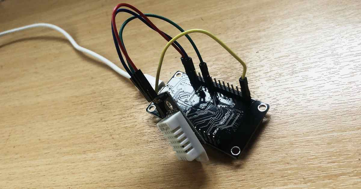
I recently built a simple temperature sensor using a NodeMCU (ESP8266) and a DHT22. This reads the temperature and humidity roughly every 30 seconds and pushes the data to a MQTT server so I can handle the data elsewhere.
The NodeMCU wakes up every 30 seconds and connects to my local WiFi network. Once connected it takes a sensor reading and publishes it to my MQTT server. It then delays for a few seconds to ensure the message is sent, then goes into deep sleep.
The deep sleep is a function I wasn’t aware of on the ESP8266 before. It just a case of wiring up D0 to RST and calling ESP.deepsleep() in the code. When the device wakes up, it’s like its been turned on for the first time.
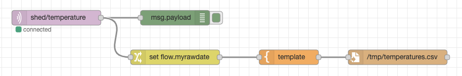
As the purpose of the sensor was to just send the data to a MQTT server in a simple format, I needed to write something to listen to the published messages the device was sending.
I was able to do this using a simple NodeRED program to listen to incoming MQTT messages, and send them to debug console, and to a CSV file for later processing.
I added a timestamp and built the CSV line using a mustache template. This is then appended to a CSV file I put in my /tmp directory.
To test the data is being logged correctly, I wrote a simple R script parse the data and plot a diagram from it. As the CSV had no header columns, I had to rename the first column names as read_csv used the first line values by default.
The Nordic Thingy:52 is a compact multi-sensor prototyping platform. It exposes a variety of configurable sensors and actuators over Bluetooth.
Modern versions of the Google Chrome browser support the Web Bluetooth API. This means we can write JavaScript that runs in a web browser to talk to Bluetooth devices. We can use this to get Chrome to talk to a Nordic Thingy:52.
Timeseries have released the Bluetooth (BLE) Connector module to the Mendix App Store. This allows developers to connect and write to Bluetooth devices from a Mendix app. These are exposed as JavaScript actions.
If we want to change the colour of the Nordic Thingy:52’s LED, how do we do this from a Mendix app?
We can use the DeviceConnect JavaScript Action in a Nanoflow to connect to a Nordic Thingy:52. The Bluetooth (BLE) Connector module doesn’t allow data to be written to a device. We need this functionality to tell the Nordic Thingy:52 what colour we want to the LED to show. So we will need to write our own JavaScript Action to do this.
Create the SetLED JavaScript Action
JavaScript Actions in Mendix are very easy to write. We create a JavaScript Action called SetLED. This needs to take 3 String parameters. A “primaryServiceUUID”, a “characteristicUUID”, and “mycolour”. The “primaryServiceUUID” describes what type of service we want to talk to. The “characteristicUUID” is the specific characteristic, in this case the LED. Finally, “mycolour” is the colour we want to show described as a CSS style rgb string (e.g. “rgb(10, 255, 10)”).
A Mendix JavaScript Action works by using a JavaScript promise to return data to a Nanoflow. Mendix has created a small scaffolded bit of JavaScript for us to change.
The first thing we need to do is to see if Bluetooth is supported. We do this by trying to access the window.gattServer. If it’s not available, we need to reject the Promise.
var gattServer = window.gattServer;
  if(gattServer){
    // Bluetooth available
  } else {
    return Promise.reject("No gatt server found");
  }
Now we need to try to access the LED characteristic on the device. We do this by creating a new Promise within which we get the primary service, then the LED characteristic. At this point we should be able to talk to the device and issue an instruction for the LED.
return new Promise((resolve, reject) => {
    gattServer.getPrimaryService(primaryServiceUUID)
    .then( (s) => {
        return s.getCharacteristic( characteristicUUID );
    })
    .then( (c) => {
        characteristic = c;
        return c;
    })
    .then(characteristic => {
        // do something with the LED
        resolve(true);
    });
});
The data is sent as binary using the writeValue method of the characteristic. We need to convert our RGB string into binary values before we send this. We can extract the individual values for R, G, and B using a regular expression. We can then insert these into a JavaScript Uint8ClampedArray. The Uint8ClampedArray prevents values under 0 and over 255. This helps us avoid buffer overflows which could cause bugs.
const match = mycolour.match(/rgba?\((\d{1,3}), ?(\d{1,3}), ?(\d{1,3})\)?(?:, ?(\d(?:\.\d?))\))?/);
let buffer = new Uint8ClampedArray(4);
buffer.set([1, match[1], match[2], match[3]], 0);

characteristic.writeValue(buffer);
Our final action should look like this…
 // This file was generated by Mendix Studio Pro.
//
// WARNING: Only the following code will be retained when actions are regenerated:
// - the code between BEGIN USER CODE and END USER CODE
// Other code you write will be lost the next time you deploy the project.

/**
 * @param {string} primaryServiceUUID
 * @param {string} characteristicUUID
 * @param {string} mycolour
 * @returns {boolean}
 */
function SetLED(primaryServiceUUID, characteristicUUID, mycolour) {
 // BEGIN USER CODE
 var gattServer = window.gattServer;
 if(gattServer){
 return new Promise((resolve, reject) => {
            gattServer.getPrimaryService(primaryServiceUUID)
            .then( (s) => {
 return s.getCharacteristic( characteristicUUID );
            })
            .then( (c) => {
                characteristic = c;
 return c;
            })
            .then(characteristic => {
 const match = mycolour.match(/rgba?\((\d{1,3}), ?(\d{1,3}), ?(\d{1,3})\)?(?:, ?(\d(?:\.\d?))\))?/);
 let buffer = new Uint8ClampedArray(4);
                buffer.set([1, match[1], match[2], match[3]], 0);

                characteristic.writeValue(buffer);
                resolve(true);
            });
        });
    } else {
 return Promise.reject("No gatt server found");
    }
 // END USER CODE
}
Now we have our JavaScript action, we can wire it into a Mendix app.
Using the SetLED JavaScript Action
We need to add a non persistable entity to hold our RGB string. We’ll call this “LED”, and add one String attribute “RGBString”.
Add a Data view to the page, and set its data source to the a new Nanoflow called CreateLED. All the Nanoflow needs to do is create an instance of our LED entity.
Mendix have provided an excelled RGB colour picker in the App Store called Color Picker. We can drop this into our Data view setting the Color Attribute field to the RGB string in our new LED entity. Set the Color Format to RGB. In the Appearance Tab set the Picker type to Hue. Now when we use the colour picker, it will save the selected value to our LED entity. That’s great, but we want to actually change the colour on Nordic Thingy:52. To do this, we need to go to Events and On change call a new Nanoflow we’ll call ChangeLED.
ChangeLED needs to first connect to the Nordic Thingy:52. We do this using the DeviceConnect JavaScript action from the Bluetooth (BLE) Connector. This takes a Primary service UUID of ” ef680100-9b35-4933-9b10-52ffa9740042″. It also takes an Optional service UUID of ” ef680300-9b35-4933-9b10-52ffa9740042″. I found these values in the example JavaScript code on Nordic’s GitHub account. When this is called it will trigger a prompt to connect to a Bluetooth device.
Once we are connected, we call our SetLED JavaScript action. The Primary service UUID is ” ef680300-9b35-4933-9b10-52ffa9740042″. This was the value we used as the optional UUID when we connected. For the Characteristic UUID we use the value “ef680301-9b35-4933-9b10-52ffa9740042” for the LED. For Mycolour we use the value in the RGBString attribute in our LED entity.
We can now run the App.
Running the App
The first time the ChangeLED Nanoflow is run it will prompt to connect to a Bluetooth device. This is where we look for our Nordic Thingy:52. Future requests are not prompted for while in the same session.
If we’ve connected to our device the LED should now be changing colour to match the value in the colour picker.
Conclusion
Hopefully this should be enough information to get you connecting to a Bluetooth device and sending data.
If you aren’t using Mendix at the moment it’s free to get started, you just need to signup for a Mendix account.
Before you plug in the dongle, you need to go into Parallels and stop sharing built in Bluetooth device to your Windows 10 instance.
Now plug the dongle in. You will need to assign the USB device to Windows 10 in Parallels when prompted.
Windows 10 will complain that the device doesn’t work. To fix this download the Windows 10 drivers. Once installed you need to restart Windows 10, but after you do Windows 10 will have a working Bluetooth connection.
Parallels has a habit of sharing the built in Bluetooth service when you restart, so make sure this is disabled if you are having problems.
It is a common requirement to be able to log data from an application. Mendix has a good logging system built in, but how do we access this from a custom Java action?
The Mendix development team have already thought of this, and have provided a method called getLogger in the Core.
To use the logger from a Java action, we first need to add a couple of imports.
Now we need to provide access to the logger. We can do this by providing a static variable which we’ll call LOG. We use the getLogger method we mentioned earlier, passing in the name of the log node name we want to use. In this case, we’ll use “RobTest” as the log node name.
// BEGIN EXTRA CODE
public static ILogNode LOG = Core.getLogger("RobTest");
// END EXTRA CODE
Now, this is in place, we can access LOG from elsewhere in our Java action.
Let’s say our action wants to log when it starts and also wants to list all the microflows available within the App. We can change the log levels, so the start notification is at “info” level, and the microflows are at “debug” level. We can do this using the following.
public java.lang.Boolean executeAction() throws Exception
{
    // BEGIN USER CODE
    LOG.info("Running executeAction()");

    for (String mf : Core.getMicroflowNames()) {
        LOG.debug("Microflow: " + mf);
    }
    return true;
    // END USER CODE
}
When we execute the Java action, we see the following on the Mendix console.
Cookie Consent
We use cookies to improve your experience on our site. By using our site, you consent to cookies.
Websites store cookies to enhance functionality and personalise your experience. You can manage your preferences, but blocking some cookies may impact site performance and services.
Essential cookies enable basic functions and are necessary for the proper function of the website.
Name
Description
Duration
Cookie Preferences
This cookie is used to store the user's cookie consent preferences.
30 days
Statistics cookies collect information anonymously. This information helps us understand how visitors use our website.
Google Analytics is a powerful tool that tracks and analyzes website traffic for informed marketing decisions.
Contains information related to marketing campaigns of the user. These are shared with Google AdWords / Google Ads when the Google Ads and Google Analytics accounts are linked together.
90 days
__utma
ID used to identify users and sessions
2 years after last activity
__utmt
Used to monitor number of Google Analytics server requests
10 minutes
__utmb
Used to distinguish new sessions and visits. This cookie is set when the GA.js javascript library is loaded and there is no existing __utmb cookie. The cookie is updated every time data is sent to the Google Analytics server.
30 minutes after last activity
__utmc
Used only with old Urchin versions of Google Analytics and not with GA.js. Was used to distinguish between new sessions and visits at the end of a session.
End of session (browser)
__utmz
Contains information about the traffic source or campaign that directed user to the website. The cookie is set when the GA.js javascript is loaded and updated when data is sent to the Google Anaytics server
6 months after last activity
__utmv
Contains custom information set by the web developer via the _setCustomVar method in Google Analytics. This cookie is updated every time new data is sent to the Google Analytics server.
2 years after last activity
__utmx
Used to determine whether a user is included in an A / B or Multivariate test.
18 months
_ga
ID used to identify users
2 years
_gali
Used by Google Analytics to determine which links on a page are being clicked
30 seconds
_ga_
ID used to identify users
2 years
_gid
ID used to identify users for 24 hours after last activity
24 hours
_gat
Used to monitor number of Google Analytics server requests when using Google Tag Manager
1 minute
Marketing cookies are used to follow visitors to websites. The intention is to show ads that are relevant and engaging to the individual user.
A video-sharing platform for users to upload, view, and share videos across various genres and topics.
Registers a unique ID on mobile devices to enable tracking based on geographical GPS location.
1 day
VISITOR_INFO1_LIVE
Tries to estimate the users' bandwidth on pages with integrated YouTube videos. Also used for marketing
179 days
PREF
This cookie stores your preferences and other information, in particular preferred language, how many search results you wish to be shown on your page, and whether or not you wish to have Google’s SafeSearch filter turned on.
10 years from set/ update
YSC
Registers a unique ID to keep statistics of what videos from YouTube the user has seen.
Session
DEVICE_INFO
Used to detect if the visitor has accepted the marketing category in the cookie banner. This cookie is necessary for GDPR-compliance of the website.
179 days
LOGIN_INFO
This cookie is used to play YouTube videos embedded on the website.
2 years
VISITOR_PRIVACY_METADATA
Youtube visitor privacy metadata cookie
180 days
You can find more information in our Cookie Policy and .